


BASIC TIMER and TIMER 0 S3F80JB
10-8
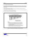
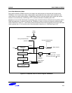
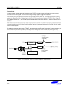
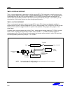
Capture Mode
In capture mode, a signal edge that is detected at the T0CAP pin opens a gate and loads the current counter
value into the T0 data register. You can select rising or falling edges to trigger this operation.
Timer 0 also gives you capture input source: the signal edge at the T0CAP pin. You select the capture input by
setting the value of the timer 0 capture input selection bit in the port 3 control register, P3CON.2, (set 1, bank 0,
EFH). When P3CON.2 is “1”, the T0CAP input is selected. When P3CON.2 is set to “0”, normal I/O port (P3.0) is
selected.
Both kinds of timer 0 interrupts can be used in capture mode: the timer 0 overflow interrupt is generated whenever
a counter overflow occurs; the timer 0 match/capture interrupt is generated whenever the counter value is loaded
into the T0 data register.
By reading the captured data value in T0DATA, and assuming a specific value for the timer 0 clock frequency, you
can calculate the pulse width (duration) of the signal that is being input at the T0CAP pin (See Figure 10-6).
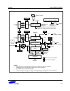
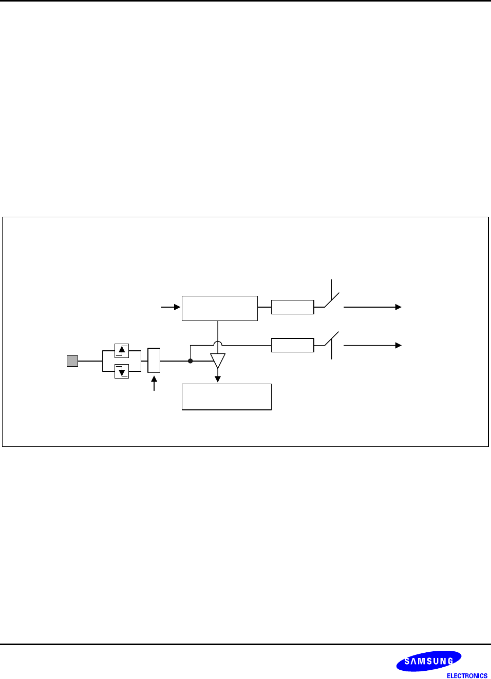
Interrupt
Enable/Disable
(T0CON.1)
IRQ0 (T0INT)
P3.0/T0CAP
Timer 0 Data Register
(T0DATA)
IRQ0 (T0OVF)
8-bit Counter
(T0CNT)
CLK
T0CON.5
T0CON.4
Interrupt
Enable/Disable
(T0CON.2)
Pending
Pending
Figure 10-6. Simplified Timer 0 Function Diagram: Capture Mode