


S3F80JB BASIC TIMER and TIMER 0
10-7
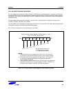
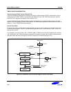
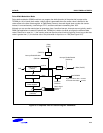
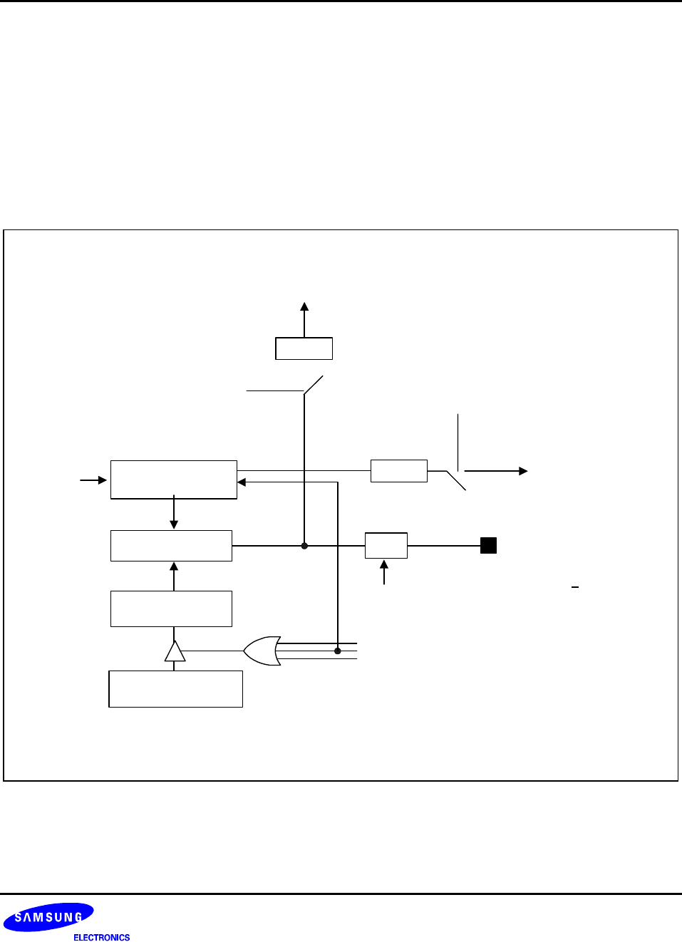
Pulse Width Modulation Mode
Pulse width modulation (PWM) mode lets you program the width (duration) of the pulse that is output at the
T0PWM pin. As in interval timer mode, a match signal is generated when the counter value is identical to the
value written to the timer 0 data register. In PWM mode, however, the match signal does not clear the counter.
Instead, it runs continuously, overflowing at ‘FFH’, and then continues incrementing from ‘00H’.
Although you can use the match signal to generate a timer 0 overflow interrupt, interrupts are not typically used in
PWM-type applications. Instead, the pulse at the T0PWM pin is held to low level as long as the reference data
value is less than or equal to ( ≤ ) the counter value and then the pulse is held to high level for as long as the data
value is greater than ( > ) the counter value. One pulse width is equal to t
CLK
× 256 (See Figure 10-5).
Match
CTL
T0CON.5
T0CON.4
P3.0/T0PWM
IRQ0 (T0OVF)
Pending
(T0PNT.0)
8-bit Counter
(T0CNT)
CLK
8-bit Comparator
Buffer Register
Timer0 Data Register
(T0DATA)
Match Signal
T0OVF
IRQ0
(T0INT)
T0CON.3
High level when data > counter
Low level when data <
counter
overflow
Pending
Interrupt Enable/Disable
(T0CON.1)
Interrupt Enable/Disable
(T0CON.2)
(T0PNT.0)
clear
Figure 10-5. Simplified Timer 0 Function Diagram: PWM Mode