


S3F80JB BASIC TIMER and TIMER 0
10-1
10 BASIC TIMER and TIMER 0
OVERVIEW
The S3F80JB has two default timers: the 8-bit basic timer and the 8-bit general-purpose timer/counter.
The 8-bit timer/counter is called timer 0.
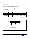
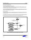
BASIC TIMER (BT)
You can use the basic timer (BT) in two different ways:
— As a watch-dog timer to provide an automatic reset mechanism in the event of a system malfunction
— To signal the end of the required oscillation stabilization interval after a reset or a Stop mode release.
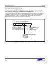
The functional components of the basic timer block are:
— Clock frequency divider (f
OSC
divided by 4096, 1024 or 128) with multiplexer
— 8-bit basic timer counter, BTCNT (FDH, Set 1, Bank0, Read-only)
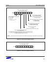
— Basic timer control register, BTCON (D3H, Set 1, Bank0, R/W)
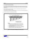
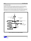
TIMER 0
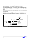
Timer 0 has three operating modes, one of which you select using the appropriate T0CON setting:
— Interval timer mode
— Capture input mode with a rising or falling edge trigger at the P3.0 pin
— PWM mode
Timer 0 has the following functional components:
— Clock frequency divider (f
OSC
divided by 4096, 256 or 8) with multiplexer
— External clock input pin (T0CK)
— 8-bit timer 0 counter (T0CNT), 8-bit comparator, and 8-bit reference data register (T0DATA)
— I/O pins for capture input (T0CAP) or match output
— Timer 0 overflow interrupt (IRQ0, vector FAH) and match/capture interrupt (IRQ0, vector FCH) generation
— Timer 0 control register, T0CON (D2H, Set 1, Bank0, R/W)
NOTE
The CPU clock should be faster than basic timer clock and timer 0 clock.