


S3F80JB DEVELOPMENT TOOLS DATA
20-3
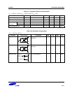
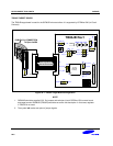
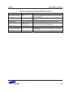
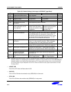
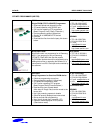
Table 20-1. Components Consisting of S3F80JB Target Board
Block Symbols
OPEN-i500 Connector J1A Connection debugging signals between emulator and 80JB
EVA target board.
TEST Board Connector J2 Connection between target board and remocon application
board.
RESET Block RESET Push Switch Generation low active reset signal of 80JB EVA-chip
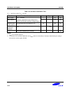
POWER Block VCC, GND, S,
nRESET LED
Generation 3.3V with 5V power inserted from external
power source or open –ice (recommend).
STOP/IDLE Display IDLE, STOP LED Indicate the status of STOP or IDLE
FLASH Serial Writing J3 Signal for writing flash ROM in tool mode. Don’t use these
in user mode.
MODE Selection JP1, JP2 Selection of Flash tool/user mode and Eva/Main-chip mode