S3F80JB ADDRESS SPACES
2-4
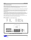
NOTES
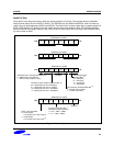
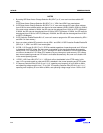
1. By setting ISP Reset Vector Change Selection Bit (3EH.7) to ‘0’, user can have the available ISP
area.
If ISP Reset Vector Change Selection Bit (3EH.7) is ‘1’, 3EH.6 and 3EH.5 are meaningless.
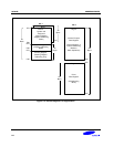
2. If ISP Reset Vector Change Selection Bit (3EH.7) is ‘0’, user must change ISP reset vector address
from 0100H to some address which user want to set reset address (0200H, 0300H, 0500H or 0900H).
If the reset vector address is 0200H, the ISP area can be assigned from 0100H to 01FFH (256bytes).
If 0300H, the ISP area can be assigned from 0100H to 02FFH (512bytes). If 0500H, the ISP area can
be assigned from 0100H to 04FFH (1024bytes). If 0900H, the ISP area can be assigned from 0100H
to 08FFH (2048bytes).
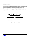
3. If ISP Protection Enable/Disable Bit is ‘0’, user can’t erase or program the ISP area selected by 3EH.1
and 3EH.0 in flash memory.
4. User can select suitable ISP protection size by 3EH.1 and 3EH.0. If ISP Protection Enable/Disable Bit
(3EH.2) is ‘1’, 3EH.1 and 3EH.0 are meaningless.
5. If IPOR / LVD Control Bit (3FH.7) is '0', IPOR is enabled regardless of operating mode and LVD block
is disabled in the STOP mode. So, the current consumption in the stop mode can be decreased by
setting IPOR / LVD Control Bit (3FH.7) to ‘0’. Although LVD block is disabled, IPOR can make power
on reset on the behalf of LVD. When CPU wakes up by any interrupts or reset sources, CPU comes
back normal operating mode and LVD block is re-enabled automatically. But, user can’t disable LVD
in the normal operating mode.
6. If IPOR / LVD Control Bit (3FH.7) is '1', LVD block will not be disabled in the STOP mode. In this
case, LVD can make power on reset and IPOR is disabled in the normal operating and STOP mode.
7. If Frequency Selection Bits (3FH.6-2) are '11110', operating max frequency is from 1MHz to 4MHz,
and operating voltage range is from 1.7V to 3.6V. If Frequency Selection Bits (3FH.6-2) are ‘11111’,
operating max frequency is from 1MHz to 8MHz, and operating voltage range is from 1.95V to 3.6V.


