


S3F80JB ADDRESS SPACES
2-10
WORKING REGISTERS
Instructions can access specific 8-bit registers or 16-bit register pairs using either 4-bit or 8-bit address fields.
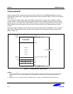
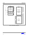
When 4-bit working register addressing is used, the 256-byte register file can be seen by the programmer as
consisting of 32 8-byte register groups or "slices." Each slice consists of eight 8-bit registers.
Using the two 8-bit register pointers, RP1 and RP0, two working register slices can be selected at any one time to
form a 16-byte working register block. Using the register pointers, you can move this 16-byte register block
anywhere in the addressable register file, except for the set 2 area.
The terms slice and block are used in this manual to help you visualize the size and relative locations of selected
working register spaces:
— One working register slice is 8 bytes (eight 8-bit working registers; R0–R7 or R8–R15)
— One working register block is 16 bytes (sixteen 8-bit working registers; R0–R15)
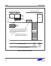
All of the registers in an 8-byte working register slice have the same binary value for their five most significant
address bits. This makes it possible for each register pointer to point to one of the 24 slices in the register file. The
base addresses for the two selected 8-byte register slices are contained in register pointers RP0 and RP1.
After a reset, RP0 and RP1 always point to the 16-byte common area in set 1 (C0H–CFH).
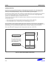
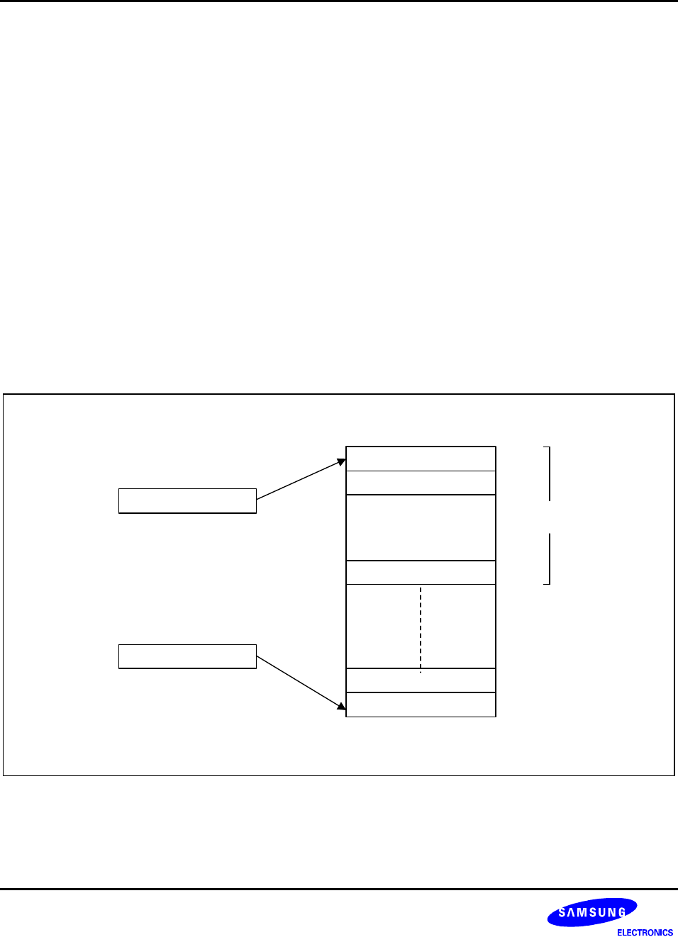
Each register pointer points to
one 8-byte slice of the register
space, selecting a total 16-byte
working register block.
1 1 1 1 1 X X X
RP1 (Registers R8-R15)
RP0 (Registers R0-R7)
Slice 32
CFH
C0H
FFH
0FH
08H
07H
00H
10H
0 0 0 0 0 X X X
~
~
Slice 1
F8H
F7H
F0H
Set 1
Only
Figure 2-6. 8-Byte Working Register Areas (Slices)