


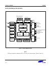

PRODUCT OVERVIEW S3F80JB
1-8
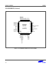
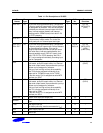
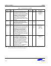
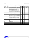
Table 1-2. Pin Descriptions of 44-QFP
Pin
Names
Pin
Type
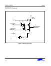
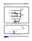
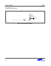
Pin Description Circuit
Type
44 Pin
No.
Shared
Functions
P0.0–P0.7 I/O I/O port with bit-programmable pins.
Configurable to input or push-pull output
mode. Pull-up resistors can be assigned
by software. Pins can be assigned
individually as external interrupt inputs
with noise filters, interrupt enable/
disable, and interrupt pending control.
SED & R(note)circuit built in P0 for STOP
releasing.
1 30–37 Ext. INT
(INT0–INT3)
(INT4)
P1.0–P1.7 I/O I/O port with bit-programmable pins.
Configurable to input mode or output
mode. Pin circuits are either push-pull or
n-channel open-drain type.
2 16
20–26
–
P2.0–P2.3
P2.4–P2.7
I/O I/O port with bit-programmable pins.
Configurable to input or push-pull output
mode. Pull-up resistors can be assigned
by software. Pins can be assigned
individually as external interrupt inputs
with noise filters, interrupt enable/
disable, and interrupt pending control.
SED & R(note) circuit built in P2.4-P2.7
for STOP releasing. Also P2.4-P2.7 can
be assigned individually as analog input
pins for Comparator.
1
42–44
1, 2,
10,11,
15
Ext. INT
(INT5–INT8)
(INT9)
(CIN0-CIN3)
P3.0 I/O I/O port with bit-programmable pin.
Configurable to input mode, push-pull
output mode, or n-channel open-drain
output mode. Input mode with a pull-up
resistor can be assigned by software.
This port 3pin has high current drive
capability. Also P3.0 can be assigned
individually as an output pin for T0PWM
or input pin for T0CAP.
In the tool mode, P3.0 is assigned as
serial MTP interface pin; SDAT
3 3 T0PWM/T0CAP
(SDAT)
NOTE: SED & R means “STOP Error Detect & Recovery”. The Stop Error Detect & Recovery Circuit is used to release stop
mode and prevent abnormal-stop mode. Refer to page 8-11.