70 English
INITIAL SET1
INTRODUCTION SETTINGS NETWORK
CONTROL
NETWORK
OPERATION
NETWORK
SETTINGS
OTHEROPERATION
4 Turn the jog dial to select “YES” and
then turn the shuttle dial clockwise.
Connected cameras are automatically detected.
When detection is completed, the display returns to the
<INITIAL SET> screen.
5 Press the [EXIT/OSD] button.
The display returns to the normal screen.
Use the following procedure to set a unique title for each
camera so that these titles can be displayed on-screen.
z Titles can be up to 10 characters in length per camera.
The following characters can be used.
z Letters: A to Z
z Numbers: 0 to 9
z Symbols: - : . / * _ (space)
z Numbers can also be entered by using the [CAMERA
SELECT] buttons 1 through 9 or the [QUAD] button.
z The display limits for monitor 2 camera title is 8 characters
for multi 9 screen display and 6 characters for multi 16
screen display.
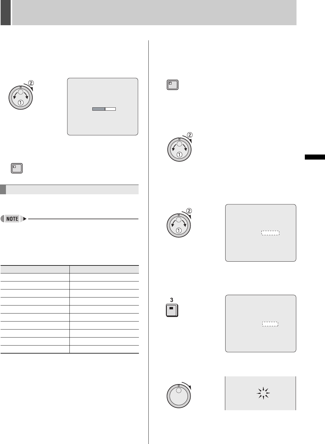
Example: Setting the title “HALL-1STFL” for Camera No. 3.
1 Press the [MENU] button.
The MENU indicator lights up and the <MAIN MENU> is
displayed.
2 Turn the jog dial to select “1.INITIAL
SET” and then turn the shuttle dial
clockwise.
The <INITIAL SET> screen is displayed.
3 Turn the jog dial to select “3.TITLE SET”
and then turn the shuttle dial clockwise.
The title setting field is displayed on the monitoring screen.
The default setting is “-----01” (camera No.).
4 Press the No. 3 [CAMERA SELECT]
button.
The video from Camera No. 3 is displayed on-screen.
5 Turn the shuttle dial clockwise.
The first character position in the title flashes.
Setting camera titles
[CAMERA SELECT] Buttons Characters that can be entered
11
22
33
44
55
66
77
88
99
QUAD 0
CAMERA DETECT !
EXIT/OSD
MENU
<TITLE SET>
CAMERA NO.01 ________01
<TITLE SET>
CAMERA NO.03 ________03
CAMERA NO.03 ________03


