


B-43
5 Buffer Memory (BFM)
5.4 Buffer Memory Details
A
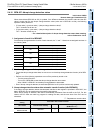
Common Items
B
FX
3U
-4AD
FX
3UC
-4AD
C
FX
3U
-4AD-ADP
D
FX
3G
-2AD-BD
E
FX
3U
-4DA
F
FX
3U
-4DA-ADP
G
FX
3G
-1DA-BD
H
FX
3U
-3A-ADP
I
FX
3U
-4AD-PT
-ADP
J
FX
3U
-4AD-PTW
-ADP
FX
3G
/FX
3U
/FX
3UC
PLC User's Manual - Analog Control Edition
FX3U-4AD/FX3UC-4AD (4-channel Analog Input)
5.4.20 BFM #109: Minimum peak value resetting / BFM #119: Maximum peak value
resetting
Initial value: H0000
Numeric data type: Hexadecimal (H)
BFM #109 can reset the minimum peak value (BFM #101 to #104), and BFM #119 can reset the maximum
peak value (BFM #111 to #114).
Channel numbers are assigned to the bits of BFM #109 and #119 to specify the channel to be subject to peak
value resetting.
Turn on each bit to reset the peak value of the corresponding channel.
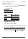
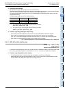
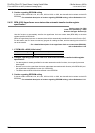
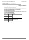
1. BFM #109/#119 bits Channel number assignment
Two or more bits can be turned on at a time.
5.4.21 BFM #125: Peak value automatic transfer to first data register specification
Setting range: 0 to 7992
Initial value (at delivery) : K200
Numeric data type: Decimal (K)
If the automatic transfer to first data register is specified in BFM #125, the minimum peak value (BFM #101 to
#104) and the maximum peak value (BFM #111 to #114) will be automatically transferred to the specified
data registers (8 points (registers) starting from the first data register specified).
When the peak value is updated, data will be automatically transferred from the 4AD to the PLC. For this
reason, the PLC does not need any program for reading the data, and the scan time of the PLC can be
shortened.
→ For a detailed description of the minimum peak value (BFM #101 to #104) and the maximum peak
value (BFM #111 to #114), refer to Subsection 5.4.19.
2. Caution regarding peak value automatic transfer-to first data register specification
• If data registers are already specified for the other automatic transfer functions, do not specify the same
data registers.
• Be sure to turn on the peak value automatic transfer function (b4 of BFM #22) and the peak value holding
function (b3 of BFM #22).
• The data written to BFM #125 will be retained in the EEPROM.
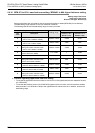
Bit No.
Description
BFM #109 BFM #119
b0
Channel-1 minimum peak value (BFM #101) resetting Channel-1 maximum peak value (BFM #111) resetting
b1
Channel-2 minimum peak value (BFM #102) resetting Channel-2 maximum peak value (BFM #112) resetting
b2
Channel-3 minimum peak value (BFM #103) resetting Channel-3 maximum peak value (BFM #113) resetting
b3
Channel-4 minimum peak value (BFM #104) resetting Channel-4 maximum peak value (BFM #114) resetting
b4 to b15 Not used.
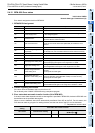
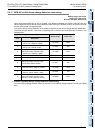
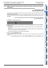
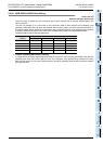
1. If "BFM #125 = K200 (initial value)"
Data will be transferred to D200 to D207 (8 points).
Specified data register Description
D200 Channel-1 minimum peak value (BFM #101)
D201 Channel-2 minimum peak value (BFM #102)
D202 Channel-3 minimum peak value (BFM #103)
D203 Channel-4 minimum peak value (BFM #104)
D204 Channel-1 maximum peak value (BFM #111)
D205 Channel-2 maximum peak value (BFM #112)
D206 Channel-3 maximum peak value (BFM #113)
D207 Channel-4 maximum peak value (BFM #114)