


B-57
7 Examples of Practical Programs
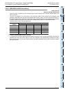
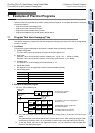
7.2 Program That Uses Convenient Functions
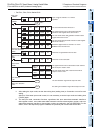
A
Common Items
B
FX
3U
-4AD
FX
3UC
-4AD
C
FX
3U
-4AD-ADP
D
FX
3G
-2AD-BD
E
FX
3U
-4DA
F
FX
3U
-4DA-ADP
G
FX
3G
-1DA-BD
H
FX
3U
-3A-ADP
I
FX
3U
-4AD-PT
-ADP
J
FX
3U
-4AD-PTW
-ADP
FX
3G
/FX
3U
/FX
3UC
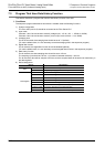
PLC User's Manual - Analog Control Edition
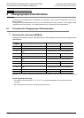
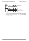
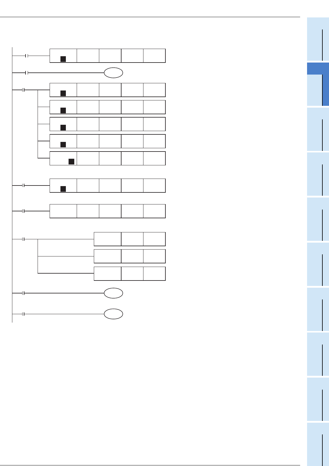
FX3U-4AD/FX3UC-4AD (4-channel Analog Input)
•For FX3G, FX3U, FX3UC Series PLCs
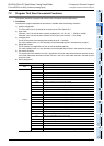
*1. After setting the input mode, set the data writing time (waiting time) to 5 seconds or more for each
setting.
After this, if the same input mode is used, it is not necessary to set the input mode and waiting time
(T0 K50) again.
*2. The set input mode, convenient functions, upper/lower limit error status data automatic transfer-to
data register number, over-scale status data automatic transfer-to data register number, and error
status data automatic transfer-to data register number are retained in the 4AD EEPROM. For this
reason, even if the sequence program is deleted, the previously set functions will still be valid.
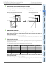
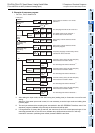
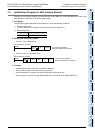
M8002
M8000
K50
T0
*1
T0
Input modes of channels 1 to 4 will be
specified.
The convenient functions will be set.
Initial pulse
The upper/lower limit error status data automatic
transfer-to data register will be set to D100.
RUN monitor
Reads the digital values of channels 1 to 4 from
BFM#10 to #13 into D0 to D3.
The over-scale status data automatic transfer-to data
register will be set to D101.
The error status data automatic transfer-to data registe
r
will be set to D102.
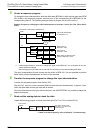
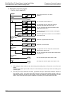
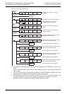
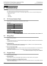
X000
Clearance of upper/
lower limit error data
Clearance of over-scale
data
X001
Clearance of upper/lower limit error data
Clearance of over-scale data
M8000
FNC 12
MOV
D100 K2Y000
The upper/lower limit error status data of each channel
will be output to Y000 to Y007.
RUN monitor
The over-scale status data of each channel will be
output to Y010 to Y017.
M0
The error detection signal will be output to Y020.
Y020
Error detection
M8
Y021
Setting error detection
The setting error detection signal will be output to Y021.
*2
*2
*2
*2
*2
FNC 79
TO
K0 K1
P
K0 H3300
FNC 79
TO
K22 K1
P
K0 H01A2
FNC 79
TO
K126 K1
P
K0 K100
FNC 79
TO
K128 K1
P
K0 K101
FNC 79
TO
K129 K1
P
K0 K102
FNC 78
FROM
K10 K4
P
K0 D0
FNC 79
TO
K99 K1
P
K0 H0003
FNC 79
TO
K28 K1K0 K0
FNC 12
MOV
D102 K4M0
FNC 12
MOV
D101 K2Y010