


E-22
5 Buffer Memory (BFM)
5.4 Buffer Memory Details
FX
3G
/FX
3U
/FX
3UC
PLC User's Manual - Analog Control Edition
FX3U-4DA (4-channel Analog Output)
2. Caution regarding EEPROM writing
If data is written to BFM #0, #5, #10 to #17, #19, #32 to #35, #50 to #54 or #60 to #63, the data will also be
written to the FX
3U-4DA EEPROM.
Do not turn off the power immediately after writing values in these buffer memories.
The maximum number of EEPROM rewrites is 10,000 times. Therefore, when creating a program, do not
frequently write data to the above buffer memories (BFM).
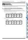
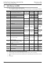
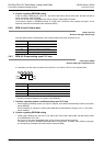
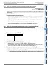
5.4.2 BFM #1 to #4: Output data
Initial value: K0
Numeric data type: Decimal (K)
Input the digital values corresponding to the analog signals to be output in BFM #1 to #4.
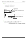
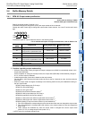
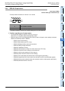
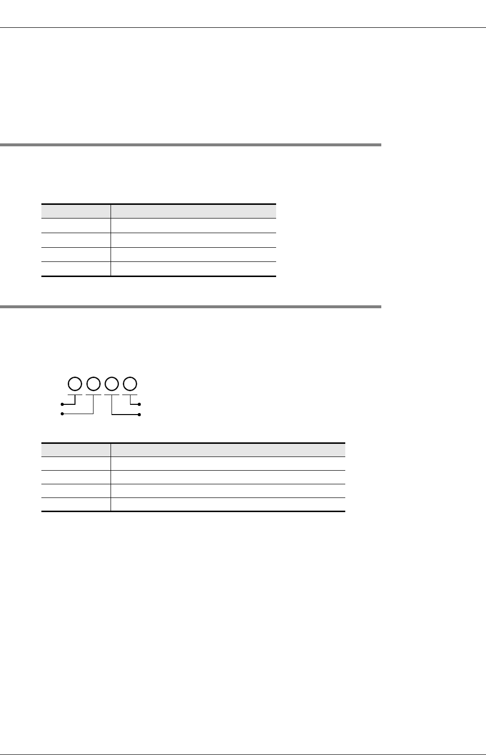
5.4.3 BFM #5: Output setting upon PLC stop
Initial value: H0000
Numeric data type: Hexadecimal (H)
It is possible to set the output conditions from channel 1 to 4 when the PLC is in the stopped state.
* The output conditions depend on the output mode (BFM #0).
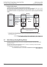
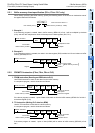
1. Cautions regarding output conditions setting upon PLC stop
• While changing the setting values, the output is stopped, and H0000 is automatically written in the output
status (BFM #6).
At the completion of change, the output status (BFM #6) will automatically change to H1111, and output
will be restarted.
2. Caution regarding EEPROM writing
• If data is set in BFM #0, #5, #10 to #17, #19, #32 to #35, #50 to #54 or #60 to #63, the data will be written
in the EEPROM of FX
3U-4DA.
Do not turn off the power immediately after writing values in these buffer memories.
The maximum number of EEPROM rewritable times is 10,000 times. Therefore, when creating a program,
do not frequently write data to the above buffer memories (BFM).
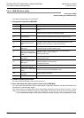
BFM number Description
#1 Data to be output from channel 1
#2 Data to be output from channel 2
#3 Data to be output from channel 3
#4 Data to be output from channel 4
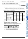
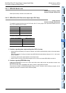
Set value (HEX) Output conditions
0 The final value during running is held.
1 The offset signal is output.*
2 The output data set in BFM #32 to #35 are output.*
3 to F Invalid (setting values unchanged)
H
ch4
ch3
ch2
ch1