


B-17
3 Wiring
3.5 Grounding
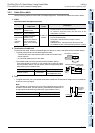
A
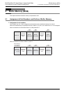
Common Items
B
FX
3U
-4AD
FX
3UC
-4AD
C
FX
3U
-4AD-ADP
D
FX
3G
-2AD-BD
E
FX
3U
-4DA
F
FX
3U
-4DA-ADP
G
FX
3G
-1DA-BD
H
FX
3U
-3A-ADP
I
FX
3U
-4AD-PT
-ADP
J
FX
3U
-4AD-PTW
-ADP
FX
3G
/FX
3U
/FX
3UC
PLC User's Manual - Analog Control Edition
FX3U-4AD/FX3UC-4AD (4-channel Analog Input)
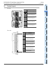
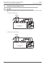
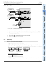
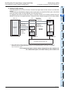
3.4.2 FX3UC-4AD
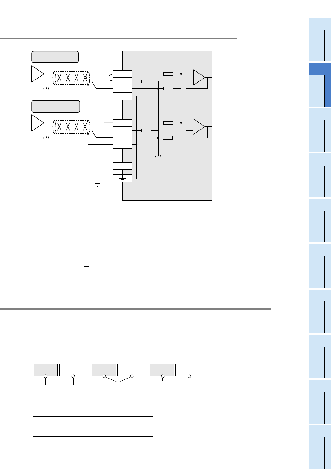
*1. Use the 2-core shielded twisted pair cable for the analog input lines, and separate the analog input
lines from the other motive power lines or inductive lines.
*2. To use the current input, be sure to short circuit the line between the V + terminal and the I
+ terminal ( : channel number).
*3. The SLD and " " terminals are connected to each other inside.
*4. Do not connect any lines to the "•" terminal.
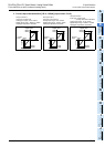
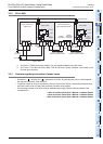
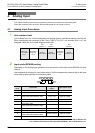
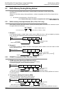
3.5 Grounding
Grounding should be performed as stated below.
• The grounding resistance should be 100Ω or less.
• Independent grounding should be performed for best results.
When independent grounding is not performed, perform "shared grounding" as shown in the following
figure.
→ For details, refer to the User’s Manual - Hardware Edition of each Series.
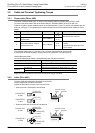
• Use the following grounding wire.
• The PLC grounding point should be close, and all grounding wires should be as short as possible.
FX3U-4AD
AWG14 (2mm
2
)
FX
3UC-4AD
AWG22-20 (0.3 to 0.5mm
2
)
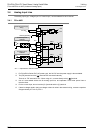
250
Ω
6.8k
Ω
ch
200k
Ω
FX
3UC
-4AD
V
+, I
+, ch
:
represents the channel number.
Terminal
block
I
+
COM
V
+
*1
I
+
COM
V
+
250
Ω
6.8k
Ω
ch
200k
Ω
*1
If current input is
selected
If voltage input is
selected
*2
•
SLD
SLD
*3
*4
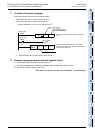
Class-D
grounding
PLC
Other
equipment
PLC
Other
equipment
PLC
Other
equipment
Shared grounding
Good condition
Common grounding
Not allowed
Independent grounding
Best condition