


E-16
5 Buffer Memory (BFM)
5.2 Buffer Memory Reading/Writing Method
FX
3G
/FX
3U
/FX
3UC
PLC User's Manual - Analog Control Edition
FX3U-4DA (4-channel Analog Output)
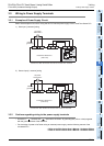
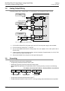
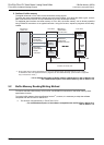
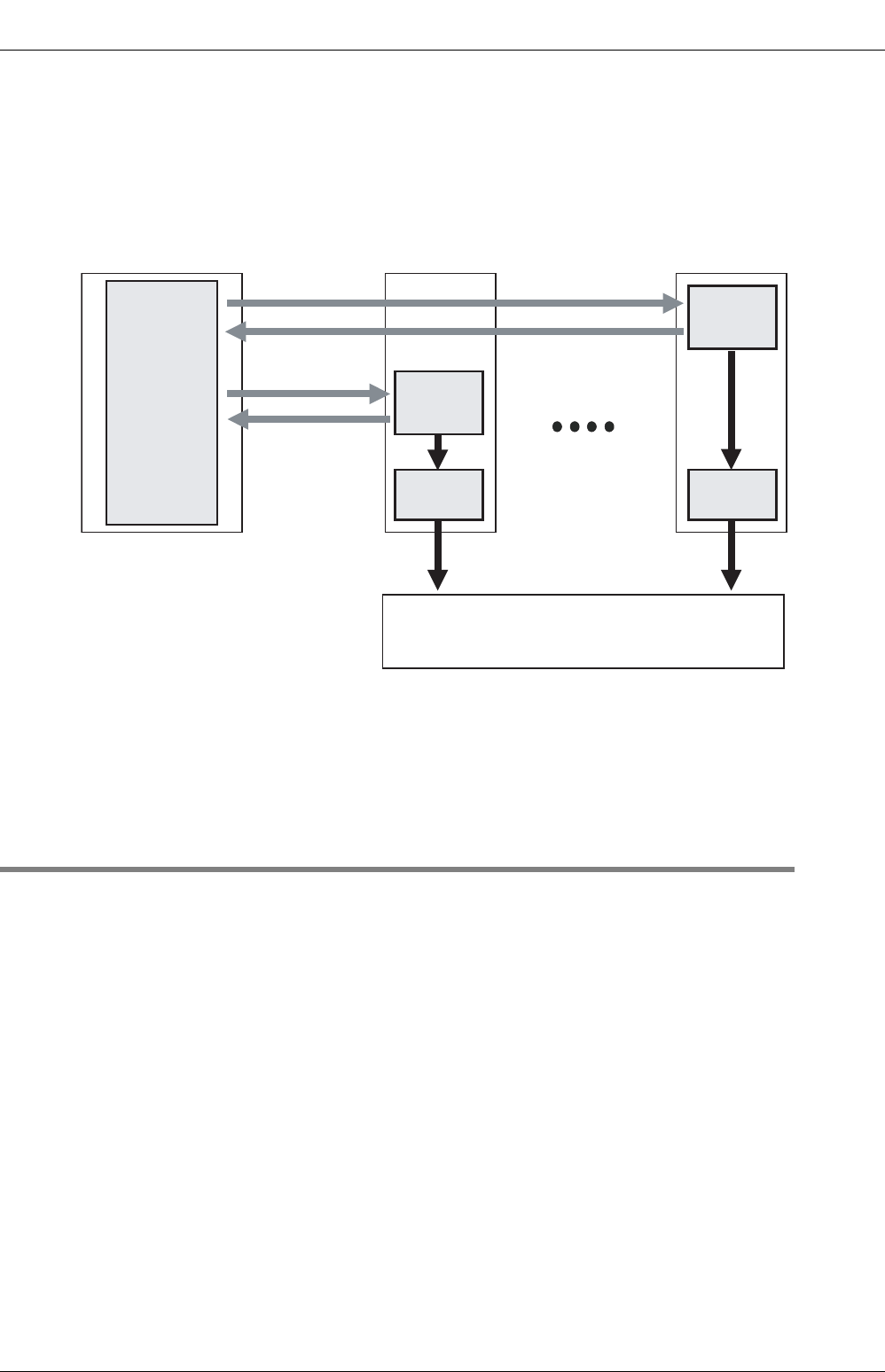
2. Outline of buffer memory
The digital values set in FX3U-4DA will be converted to analog signals.
To switch the output mode between voltage output and current output, or to adjust the offset or gain, numeric
data will be sent from the main unit and written/set in the FX
3U-4DA buffer memory.
To read/write data from/into the buffer memory of FX
3U-4DA, the buffer memory can be directly specified
using FROM/TO instructions or an applied instruction. Using this function, sequence programs can be easily
created.
→ For a detailed description of buffer memory reading/writing, refer to Section 5.2.
→ For a detailed description of the buffer memory, refer to Section 5.4.
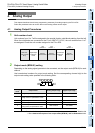
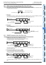
5.2 Buffer Memory Reading/Writing Method
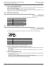
To read or write the buffer memory of FX3U-4DA, use FROM/TO instructions or the buffer memory direct
specification function
*1
.
To use the buffer memory direct specification function
*1
, however, it is necessary to adopt the software
compatible with the FX3U/FX3UC Series PLC.
*1. This function is supported only in FX
3U/FX3UC PLCs.
→ For a detailed description of the software compatible with the FX
3U/FX3UC Series PLC,
refer to Section 1.4.
*1. Since buffer memory direct specification (U\G) can directly specify the buffer memory in the source
or destination area of an applied instruction, programs can be created efficiently. (This function is supported
only in FX
3U/FX3UC PLCs.)
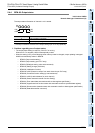
FX3U/FX3UC
Series PLC
Sequence
program
FX3U-4DA
Buffer
memory
D/A
conversion
FX3U-4DA
Buffer
memory
D/A
conversion
Analog dataAnalog data
Digital
value
Digital
value
Inverter, DC motor, etc.
• TO instruction
• FROM
instruction
• BFM direct
specification
*1
• BFM direct
specification
*1
• TO instruction
• BFM direct
specification
*1
• FROM instruction
• BFM direct
specification
*1