


C-25
4 Programming
4.8 Basic Program Example
FX
3G
/FX
3U
/FX
3UC
PLC User's Manual - Analog Control Edition
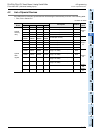
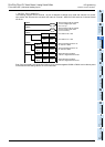
FX3U-4AD-ADP (4-channel analog Input)
A
Common Items
B
FX
3U
-4AD
FX
3UC
-4AD
C
FX
3U
-4AD-ADP
D
FX
3G
-2AD-BD
E
FX
3U
-4DA
F
FX
3U
-4DA-ADP
G
FX
3G
-1DA-BD
H
FX
3U
-3A-ADP
I
FX
3U
-4AD-PT
-ADP
J
FX
3U
-4AD-PTW
-ADP
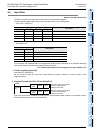
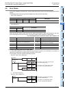
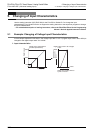
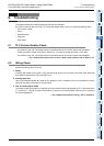
•For FX3U, FX3UC Series PLC
The following program will set channel 1 of the 1st adapter to voltage input mode and channel 2 to current
input mode, and will store the converted A/D value of channel-1 data into D100 and that of channel-2 data
into D101.
Even if the input data is not stored into D100 or D101, the data registers D8260 or D8261 can be directly used
in the timer/counter setting value or in a PID instruction.
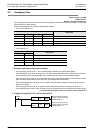
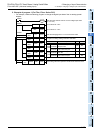
M8001
M8260
M8000
M8261
Sets the input mode of channel
1 to the voltage input mode
(0 V to 10 V).
Sets the input mode of channel
2 to the current input mode
(4 mA to 20 mA).
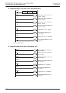
M8002
RST D8268.6
RST D8268.7
Error status: b6 = OFF
Error status: b7 = OFF
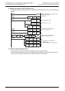
M8000
FNC 12
MOV
K5 D8264
FNC 12
MOV
K5 D8265
Sets the averaging time to "5"
for channel-1 data.
Sets the averaging time to "5"
for channel-2 data.
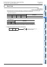
M8000
FNC 12
MOV
D8260 D100
FNC 12
MOV
D8261 D101
Stores the A/D converted
channel-1 digital data into D100.
Stores the A/D converted
channel-2 digital data into D101.