


E-15
5 Buffer Memory (BFM)
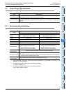
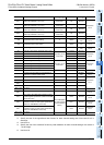
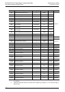
5.1 Assignment of Unit Numbers and Outline of Buffer Memory
A
Common Items
B
FX
3U
-4AD
FX
3UC
-4AD
C
FX
3U
-4AD-ADP
D
FX
3G
-2AD-BD
E
FX
3U
-4DA
F
FX
3U
-4DA-ADP
G
FX
3G
-1DA-BD
H
FX
3U
-3A-ADP
I
FX
3U
-4AD-PT
-ADP
J
FX
3U
-4AD-PTW
-ADP
FX
3G
/FX
3U
/FX
3UC
PLC User's Manual - Analog Control Edition
FX3U-4DA (4-channel Analog Output)
5. Buffer Memory (BFM)
This chapter describes the buffer memory incorporated in FX3U-4DA.
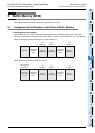
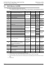
5.1 Assignment of Unit Numbers and Outline of Buffer Memory
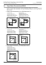
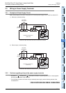
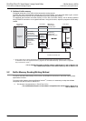
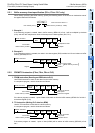
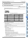
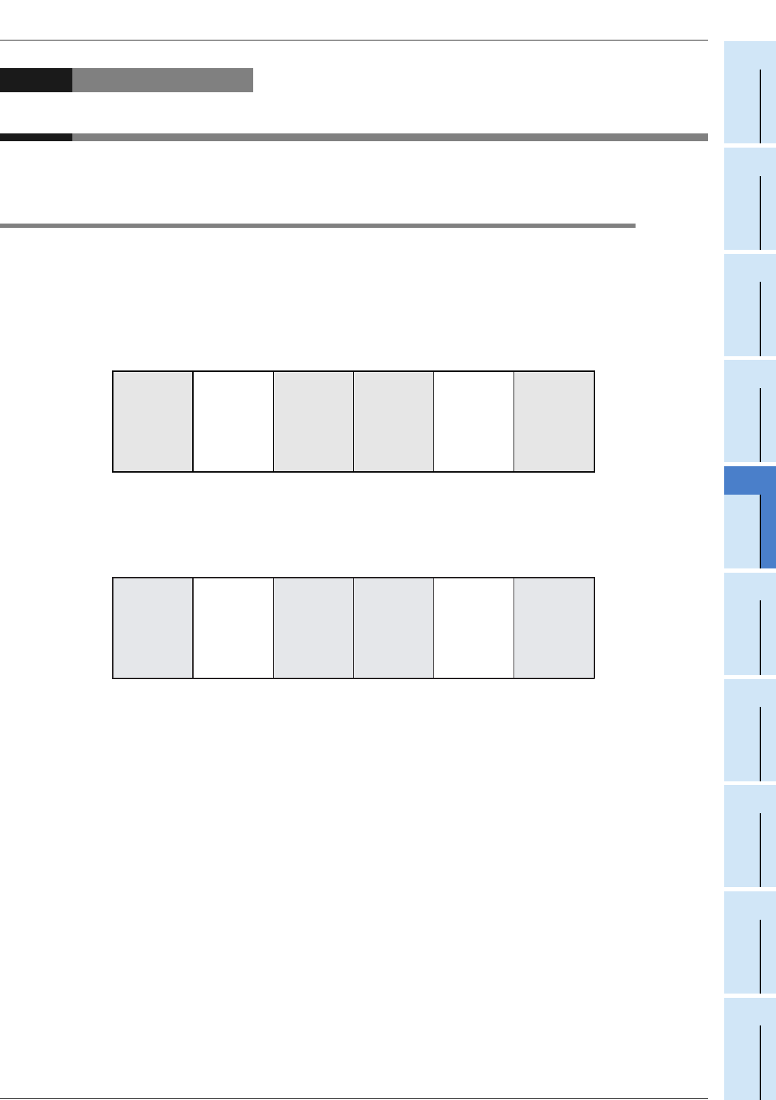
1. Assignment of unit numbers
Unit numbers from 0 to 7 will be assigned to the special function units/blocks starting from the left one.
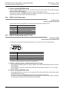
When the units/blocks are connected to the FX
3UC-32MT-LT(-2) PLC, unit numbers from 1 to 7 are assigned.
When connected to the FX
3G/FX3U/FX3UC (D, DSS) Series PLC
When connected to the FX
3UC-32MT-LT(-2) PLC
Main unit
Input/output
extension
block
Special
function block
Special
function block
Input/output
extension
block
Special
function unit
Unit
number: 0
Unit
number: 1
Unit
number: 2
Main unit
(FX3UC-32MT
-LT(-2))
Input/output
extension
block
Special
function block
Special
function block
Input/output
extension
block
Special
function unit
Unit number: 0
(Incorporated
CC-Link/LT)
Unit
number: 1
Unit
number: 2
Unit
number: 3