


E-56
8 Examples of Practical Programs
8.1 Example of Program for Analog Output Operation (Regular Operation)
FX
3G
/FX
3U
/FX
3UC
PLC User's Manual - Analog Control Edition
FX3U-4DA (4-channel Analog Output)
8. Examples of Practical Programs
8.1 Example of Program for Analog Output Operation (Regular Operation)
When you want to use the initial output characteristics but do not need to use the status information, you can
operate the PLC with a simple program as shown below.
1. Conditions
The sequence program described in this section is under the following conditions.
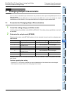
1) System configuration
FX
3U-4DA (unit No.0) should be connected to the FX3U Series PLC.
2) Output mode
Channels 1 and 2 should be set to mode 0 (voltage output, -10 V to +10 V).
Channel 3 should be set to mode 3 (current output, 4 mA to 20 mA).
Channel 4 should be set to mode 2 (current output, 0 mA to 20 mA).
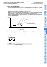
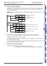
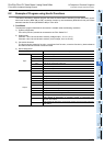
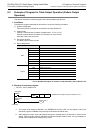
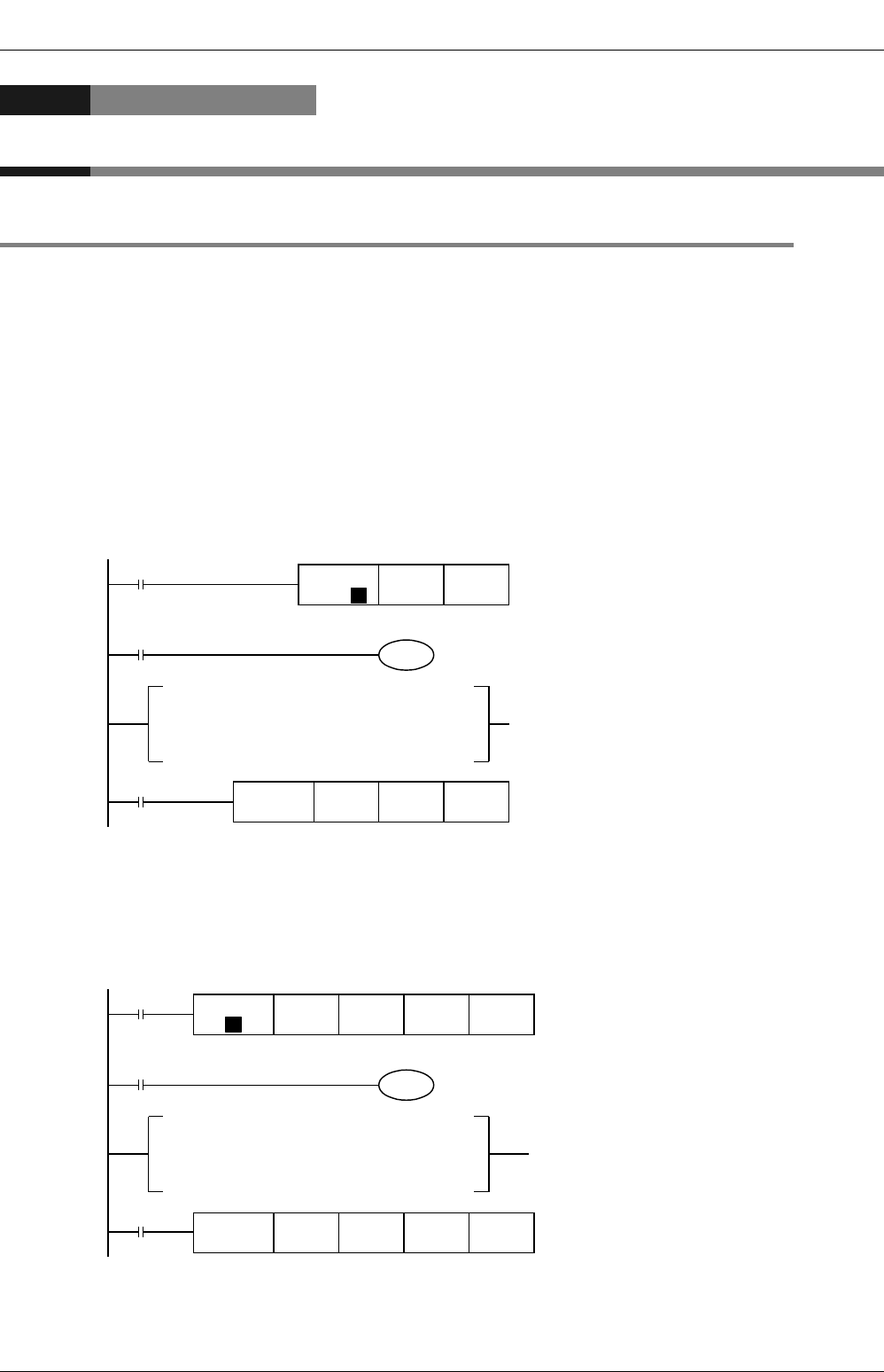
-For FX
3U, FX3UC Series PLCs
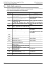
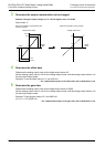
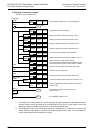
-For FX
3G, FX3U, FX3UC Series PLCs
M8002
FNC 12
MOV
H2300 U0\G0
P
M8000
K50
T0
*
T0
Transfer H2300 to BFM #0 (output modes of
channels 1 to 4).
ch1 and ch2: Voltage output (-10 to +10 V),
output mode 0
ch3: Current output (4 mA to 20 mA), output
mode 3
ch4: Current output (0 mA to 20 mA), output
mode 2
Initial pulse
FNC 15
BMOV
D0 U0\G1 K4
RUN monitor
D0
→
BFM #1 (output to channel 1)
D1
→
BFM #2 (output to channel 2)
D2
→
BFM #3 (output to channel 3)
D3
→
BFM #4 (output to channel 4)
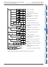
Data to be output to channel 1 is written in D0.
Data to be output to channel 2 is written in D1.
Data to be output to channel 3 is written in D2.
Data to be output to channel 4 is written in D3.
Store the data to be output to channels 1 to 4
in D0 to D3 in the following ranges.
D0 and D1: -32000 to +32000
D2 and D3: 0 to 32000
* After setting the output mode, set the data writing time (waiting time) to 5 seconds or more for each
setting. The specified output mode will be retained even if power failure occurs. After the output mode
is specified, if the same output mode is used, it is not necessary to set the output mode and the waiting
time (T0 K50).
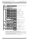
M8002
M8000
K50
T0
*
T0
Transfer H2300 to BFM #0 (output modes of
channels 1 to 4).
ch1 and ch2: Voltage output (-10 to +10 V),
output mode 0
ch3: Current output (4 mA to 20 mA), output
mode 3
ch4: Current output (0 mA to 20 mA), output
mode 2
Initial pulse
RUN monitor
D0
→
BFM #1 (output to channel 1)
D1
→
BFM #2 (output to channel 2)
D2
→
BFM #3 (output to channel 3)
D3
→
BFM #4 (output to channel 4)
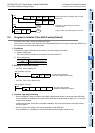
Data to be output to channel 1 is written in D0.
Data to be output to channel 2 is written in D1.
Data to be output to channel 3 is written in D2.
Data to be output to channel 4 is written in D3.
Store the data to be output to channels 1 to 4
in D0 to D3 in the following ranges.
D0 and D1: -32000 to +32000
D2 and D3: 0 to 32000
* After setting the output mode, set the data writing time (waiting time) to 5 seconds or more for each
setting. The specified output mode will be retained even if power failure occurs. After the output mode
is specified, if the same output mode is used, it is not necessary to set the output mode and the waiting
time (T0 K50).
FNC 79
TO
K0 K1
P
K0 H2300
FNC 79
TO
K1 K4K0 D0