


K-14
3 Wiring
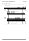
3.4 Selection of the Resistance Thermometer Sensor
FX
3G
/FX
3U
/FX
3UC
PLC User's Manual - Analog Control Edition
FX3U-4AD-PNK-ADP (4-channel Resistance Thermometer Data Input)
3.4 Selection of the Resistance Thermometer Sensor
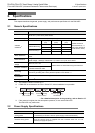
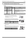
Select the Pt1000/Ni1000 (2-wire or 3-wire sensors) resistance thermometer sensor.
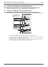
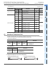
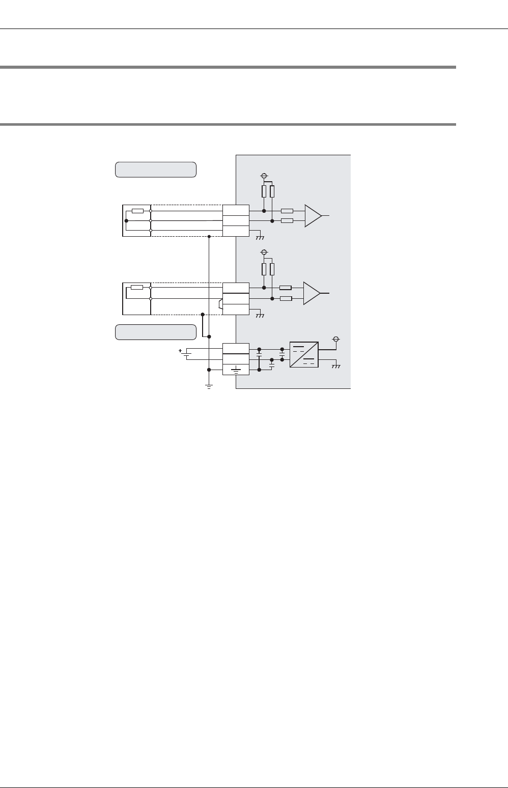
3.5 Wiring of the Resistance Thermomester Sensor
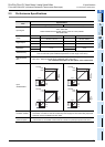
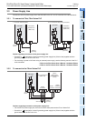
Wiring depends on the resistance thermometer sensor type selected. Refer to the following wiring diagrams:
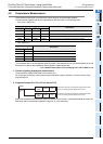
*1. 24V DC service power supply of the FX
3G/FX3U Series PLC can also be used.
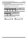
*2. When using a 2-wire temperature sensor type, short-circuit the [L -] terminal and the [I -] terminal.
For the lead wire use a 10Ω resistance or less per line.
*3. Separate the cable of the platinum resistance themometer sensor from the other power cables or
areas easily affected by inductive noise (of the commercial power, etc.).
1MΩ
ch
PNK-ADP
Class-D grounding
+5V
24+
24-
Shield wire
Terminal
block
24V DC
*1
L+, L-, I-, ch: represents the channel number.
3-wire
sensors
type
1MΩ
47kΩ47kΩ
+5V
1MΩ
ch
+5V
1MΩ
47kΩ47kΩ
2-wire
sensors
type
L-
I-
L+
L-
I-
L+
*2
*3
Resistance thermometer
wiring
External power supply
wiring