


E-62
8 Examples of Practical Programs
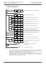
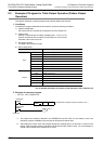
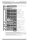
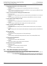
8.3 Example of Program for Table Output Operation (Pattern Output Operation)
FX
3G
/FX
3U
/FX
3UC
PLC User's Manual - Analog Control Edition
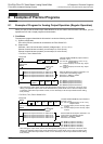
FX3U-4DA (4-channel Analog Output)
•For FX3G, FX3U, FX3UC Series PLCs
*1. The output mode setting is retained in the EEPROM of the FX
3U-4DA. For this reason, even if the
sequence program is deleted, the previously set functions will still be valid.
*2. After setting the output mode, set the data writing time (waiting time) to 5 seconds or more for each
setting. After the output mode is specified, and the same output mode is used, it is not necessary to
set the output mode and the waiting time (T0 K50).
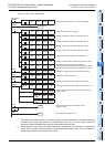
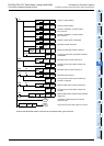
*3. Execute the data table transfer command as a pulse execution type instruction.
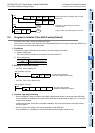
T0
Channel-1 output pattern
Number of repetitions of output of table
from channel 1
X000
Start table output function (channel 1)
Turning-off of M1 when output of table from
channel 3 is stopped
Turning-on of M1 when table is output from
channel 3
Number of repetitions of output of table
from channel 3
Number of head device in data table
Data table transfer command
Readout of data table transfer command
Turning-on of M0 At the completion of transfer
of data table
Start table output function (channel 3)
Turning-on of M1 when table is output from
channel 3
Stop table output function
Restart of table output function (channel 3)
M10
SET M0
SET M1
M1
M1
RST M1
X002
M1
SET M1
Channel-3 output pattern
X001
X000
*3
M8002
M8000
K50
T0
Specification of output modes of channels 1 to 4
Initial pulse
RUN monitor
*1
*2
FNC 79
TO
K0 K1
P
K0 HF2F0
FNC 79
TO
K81 K1
P
K0 K1
FNC 79
TO
K83 K1
P
K0 K2
FNC 79
TO
K85 K1
P
K0 K5
FNC 79
TO
K87 K1
P
K0 K0
FNC 79
TO
K98 K1
P
K0 K5000
FNC 79
TO
K99 K1
P
K0 H0001
FNC 78
FROM
K99 K1K0 D100
FNC 12
MOV
D100 K4M10
FNC 79
TO
K80 K1
P
K0 H0100
FNC 79
TO
K80 K1
P
K0 H0101
FNC 79
TO
K80 K1
P
K0 H0000
FNC 79
TO
K80 K1
P
K0 H0100
Continued