


E-12
3 Wiring
3.4 Analog Output Wiring
FX
3G
/FX
3U
/FX
3UC
PLC User's Manual - Analog Control Edition
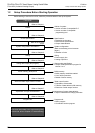
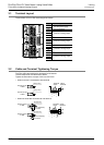
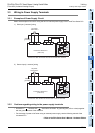
FX3U-4DA (4-channel Analog Output)
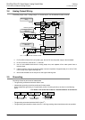
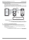
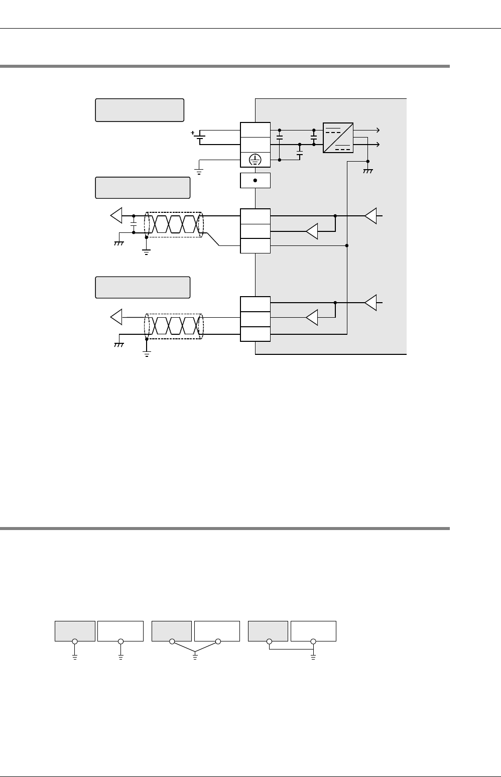
3.4 Analog Output Wiring
The analog output mode, "voltage output "or "current output", can be selected for each channel.
*1. For FX
3G/FX3U Series PLC (AC power type), the 24V DC service power supply is also available.
*2. Do not connect any wires to the "
•
" terminal.
*3. Use a 2-core twisted shield wire for analog output wire, and separate it from other power lines or
inductive lines.
*4. If there is ripple or noise in the output voltage, connect a capacitor of approximately 0.1 to 0.47μF 25V
in the vicinity of the signal receiving side.
*5. Ground the shielded wire at one point on the signal receiving side.
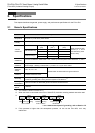
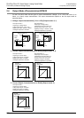
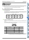
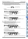
3.5 Grounding
Grounding should be performed as stated below.
• The grounding resistance should be 100Ω or less.
• Independent grounding should be performed for best results.
When independent grounding is not performed, perform "shared grounding" as shown in the following
figure.
→ For details, refer to the User’s Manual - Hardware Edition of each Series.
• The grounding wire size should be AWG14 (2mm
2
.)
• The grounding point should be close to the PLC, and all grounding wires should be as short as possible.
FX
3U
-4DA
+15V
I+
VI-
V+
24+
24-
-15V
I+
VI-
V+
ch
:
represents the channel number.
ch
Shield *3
24V DC
If voltage output is
selected
If current output is
selected
External power supply
wiring
*1
ch
ch
Class-D grounding
*2
ch
Shield *3
*4 *5
*5
PLC
Other
equipment
PLC
Other
equipment
PLC
Other
equipment
Shared grounding
Good condition
Common grounding
Not allowed
Independent grounding
Best condition