A-38
4 Comparison of Performance Specifications
4.3 Mixed Analog Input/Output
FX
3G
/FX
3U
/FX
3UC
PLC User's Manual - Analog Control Edition
Common Items
4.3 Mixed Analog Input/Output
4.3.3 FX0N-3A
*1. Combined use of voltage and current inputs is not possible.
*2. Adjustment of the volume (offset or gain) value will change the resolution.
*3. Adjustment of the offset or gain value will change the resolution.
Specifications
FX0N-3A
Voltage input Current input Voltage output Current output
Number of
input/output
points
2ch 1ch
Analog input/
output range
*1
0V to 10V DC
0V to 5V DC
(Input resistance: 200kΩ)
4mA to 20mA DC
(Input resistance: 250Ω)
0V to 10V DC
0V to 5V DC
(External load: 1k to 1MΩ)
4mA to 20mA DC
(External load: 500Ω)
Absolute
maximum
input
-0.5V,
+15V
-2mA,
+60mA
--
Offset
*2*3
If the digital value is "0":
0V to 1V
If the digital value is "0":
0mA to 4mA
If the digital value is "0":
0V to 1V
If the digital value is "0":
4mA
Gain
*2*3
If the digital value is "250":
5V to 10V
If the digital value is "250":
20mA
If the digital value is "250":
5V to 10V
If the digital value is "250":
20mA
Digital input/
output
0 to 250
8 bits, binary
0 to 250
8 bits, binary
Resolution
*3
40mV(10V×1/250) 64μA(16mA×1/250) 40mV(10V×1/250) 64μA(16mA×1/250)
Overall
accuracy
±0.1V ±0.16mA ±0.1V ±0.16mA
Time required
for conversion
TO instruction processing time × 2 + FROM instruction processing time
(operation synchronized with sequence program)
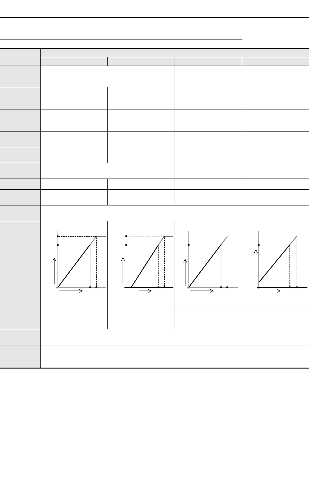
I/O
characteristics
If the input data consists of 9 bits or more, only the
lower 8 bits will be valid, and the other bits will be
ignored.
Insulation
method
• The photocoupler is used to insulate the analog input and output area from the PLC.
• Channels are not insulated from each other.
Number of I/O
points
occupied
8 points (Taken from either the input or output points of the PLC.)
0
250
10V
255
Analog input
Digital output
10.200V
255
0
250
20mA
Analog input
Digital output
4mA
20.320mA
0
10V
250
Digital input
Analog output
255
0
20mA
250
Digital input
Analog output
4mA
255


