


E-31
5 Buffer Memory (BFM)
5.4 Buffer Memory Details
A
Common Items
B
FX
3U
-4AD
FX
3UC
-4AD
C
FX
3U
-4AD-ADP
D
FX
3G
-2AD-BD
E
FX
3U
-4DA
F
FX
3U
-4DA-ADP
G
FX
3G
-1DA-BD
H
FX
3U
-3A-ADP
I
FX
3U
-4AD-PT
-ADP
J
FX
3U
-4AD-PTW
-ADP
FX
3G
/FX
3U
/FX
3UC
PLC User's Manual - Analog Control Edition
FX3U-4DA (4-channel Analog Output)
5.4.14 BFM #39: Upper/lower limit function status
Initial value: H0000
Numeric data type: Hexadecimal (H)
When any of the output data (BFM #1 to #4) is out of range between the lower limit and the upper limit (BFM
#41 to #48), the relevant bit is turned on.
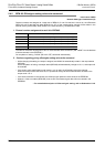
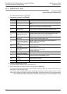
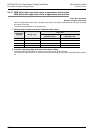
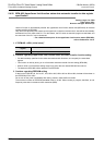
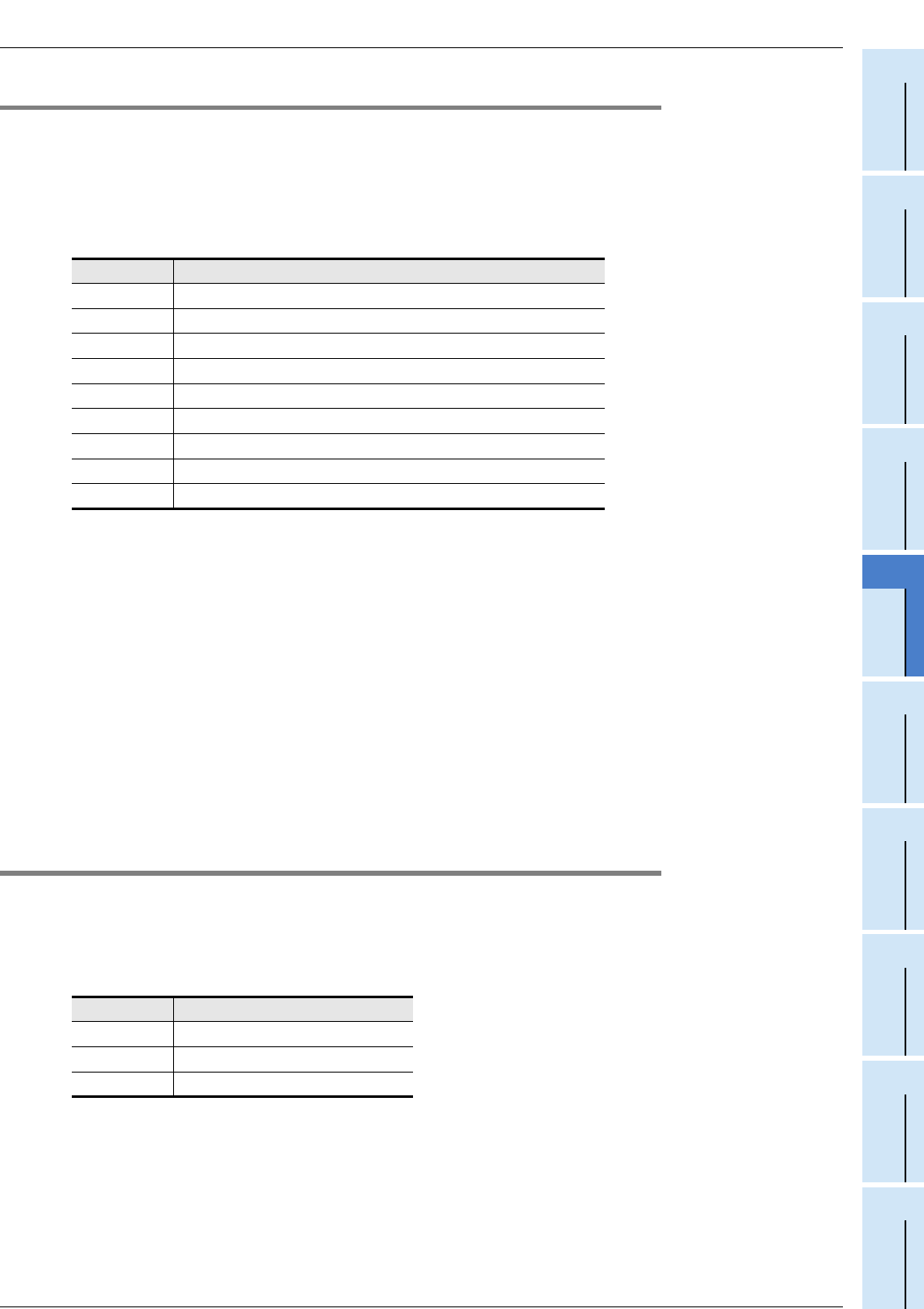
1. Assignment to each bit of BFM #39
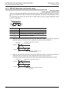
2. Cautions regarding use of the upper/lower limit function status
• The ON bits of the upper/lower limit function status are latched after the output data has returned to the
specified ranges between the upper and lower limits.
• The upper/lower limit function status can be reset by the following methods.
- Use the upper/lower limit function status reset function (BFM #40).
- Turn the power supply off then on.
3. Upper/lower limit automatic transfer function (b1 of BFM #60)
If the upper/lower limit automatic transfer data register is specified in BFM #62, the data in BFM #39 can be
transferred to a specified data register.
Only when an error is detected, data will be automatically transferred from the FX
3U-4DA to the PLC. For this
reason, the PLC does not need the program for reading data, and the scan time of the PLC can be shortened.
→ For a detailed description of the status automatic transfer function, refer to Subsection 5.4.18.
5.4.15 BFM #40: Clearance of upper/lower limit function status
Initial value: H0000
Numeric data type: Hexadecimal (H)
The flags can be reset by turning on the following bits of BFM #40.
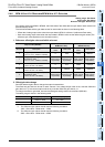
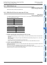
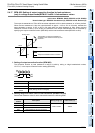
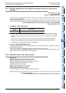
1. Assignment to each bit of BFM #40
2. Operation to be performed after resetting
At the completion of status reset, the bits of BFM #40 will automatically turn off.
Bit Description
b0 Data output from channel 1 < Lower limit (BFM #41)
b1 Data output from channel 1 > Upper limit (BFM #45)
b2 Data output from channel 2 < Lower limit (BFM #42)
b3 Data output from channel 2 > Upper limit (BFM #46)
b4 Data output from channel 3 < Lower limit (BFM #43)
b5 Data output from channel 3 > Upper limit (BFM #47)
b6 Data output from channel 4 < Lower limit (BFM #44)
b7 Data output from channel 4 > Upper limit (BFM #48)
b8 to b15 Not used
Bit Description
b0 Clearance of lower limit status
b1 Clearance of upper limit status
b2 to b15 Invalid