


E-27
5 Buffer Memory (BFM)
5.4 Buffer Memory Details
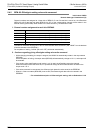
A
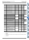
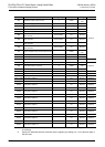
Common Items
B
FX
3U
-4AD
FX
3UC
-4AD
C
FX
3U
-4AD-ADP
D
FX
3G
-2AD-BD
E
FX
3U
-4DA
F
FX
3U
-4DA-ADP
G
FX
3G
-1DA-BD
H
FX
3U
-3A-ADP
I
FX
3U
-4AD-PT
-ADP
J
FX
3U
-4AD-PTW
-ADP
FX
3G
/FX
3U
/FX
3UC
PLC User's Manual - Analog Control Edition
FX3U-4DA (4-channel Analog Output)
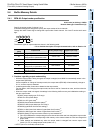
5.4.8 BFM #20: Initialization function (resetting to factory default status)
Setting range: K0 or K1
Initial value: K0
Numeric data type: Decimal (K)
When K1 is set in BFM #20, all functions and all buffer memory (BFM #0 to #3098) will be initialized to the
default status.
When BFM #20 is not K0 or K1, this function is invalid. (The settings will not be changed, and the functions
will not be initialized.)
1. Cautions regarding initialization function
• During initialization, output is stopped, and H0000 is automatically written in the output status (BFM #6).
At the completion of initialization, the output status (BFM #6) will automatically change to H1111, and
output will be restarted.
• It takes approximately 5 seconds to initialize all the data. Do not set (write) data in the buffer memory
during this period.
• Priority is given to the setting of the value change prohibition mode (BFM #19).
• At the completion of initialization, the value of BFM #20 will automatically change to K0.
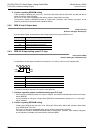
5.4.9 BFM #28: Disconnection detection status (only in current output mode)
Initial value: H0000
Numeric data type: Hexadecimal (H)
When a wire-break is detected, the bit corresponding to the relevant channel will turn on.
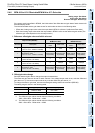
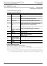
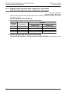
1. Assignment to each bit of BFM #28
2. Cautions regarding use of disconnection detection status
• When any of b0 to b3 is turned on, b11 of the error status (BFM #29) is turned on.
• The disconnection detection status is valid only if the output mode (BFM #0) is the current output mode
(mode 2 to 4). In other output modes, each corresponding bit of BFM #28 stays off.
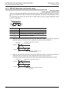
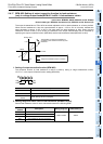
3. Disconnection detection status automatic transfer function (b2 of BFM #60)
If the disconnection detection status with automatic transfer-to data register is specified in BFM #63, the data
in BFM #28 can be transferred to the specified data register.
Only when wire-break is detected, data will be automatically transferred from FX
3U-4DA to the PLC. For this
reason, the PLC does not need the program for reading data, and the scan time of the PLC can be shortened.
→ For a detailed description of the status automatic transfer function, refer to Subsection 5.4.18.
Bit No. Description
b0 Wire-break in channel 1
b1 Wire-break in channel 2
b2 Wire-break in channel 3
b3 Wire-break in channel 4
b4 to b15 Not used