


G-14
4 Programming
4.2 List of Special Devices
FX
3G
/FX
3U
/FX
3UC
PLC User's Manual - Analog Control Edition
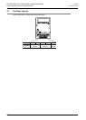
FX3G-1DA-BD (1-channel analog Output)
4.2 List of Special Devices
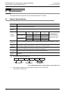
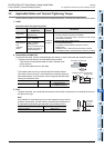
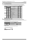
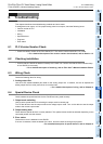
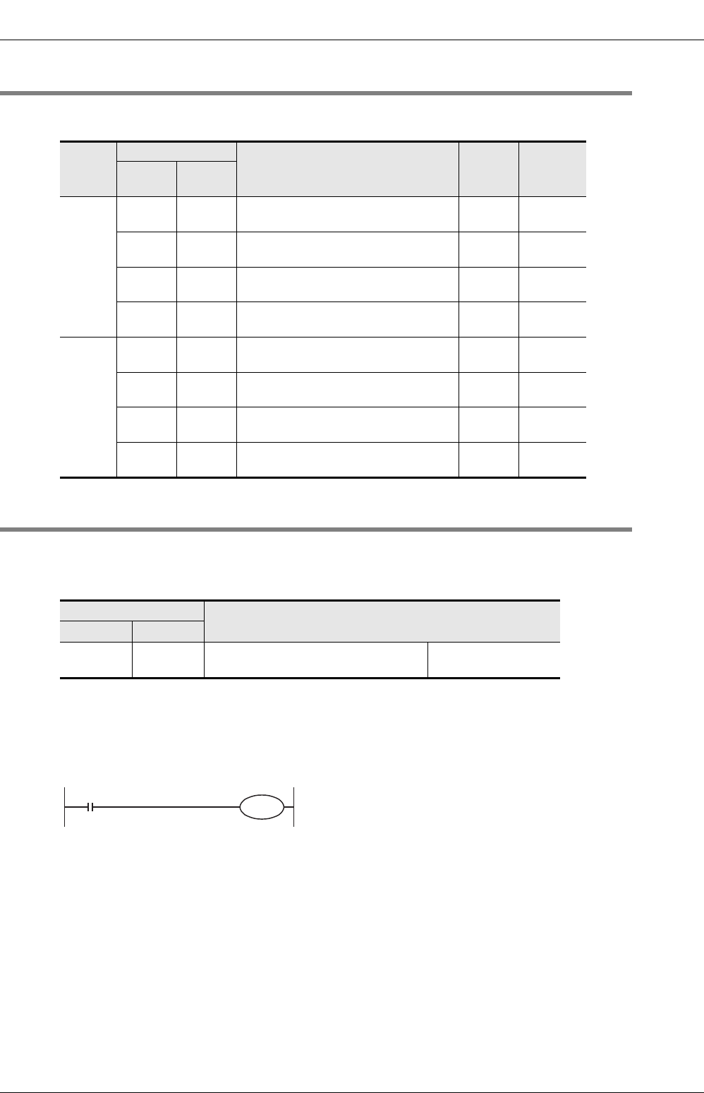
If 1DA-BD is connected, special devices will be assigned automatically as shown in the following table:
R: Read / W: Write
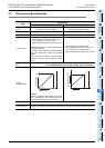
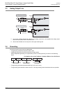
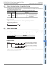
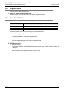
4.3 Switching of Output Mode
Turn the special auxiliary relay on/off to switch the output mode of 1DA-BD between the current output mode
and the voltage output mode.
To switch the output mode, use the following special auxiliary relays:
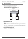
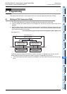
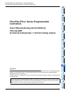
1. Program Example
To switch the output mode, create a sequence program as follows:
Special
device
Device number
Description Attribute Reference
1st
board
2nd
board
Special
auxiliary
relay
M8260 M8270 Switches the output mode. R/W
Section
4.3
M8261 to
M8263
M8271 to
M8273
Unused (Do not use.) - -
M8264 M8274
Sets the cancel of output holding
function.
R/W
Section
4.4
M8265 to
M8269
M8275 to
M8279
Unused (Do not use.) - -
Special
data
register
D8260 D8270 Output setting data R/W
Section
4.5
D8261 to
D8267
D8271 to
D8277
Unused (Do not use.) - -
D8268 D8278 Error status R/W
Section
4.6
D8269 D8279 Model code = 4 R
Section
4.7
Special auxiliary relay
Description
1st board 2nd board
M8260 M8270 Switches the output mode.
OFF:Voltage output
ON :Current output
To switch the channel output mode of the
1st analog board to the voltage output mode:
M8001
M8260
Normally OFF