


E-21
5 Buffer Memory (BFM)
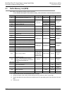
5.4 Buffer Memory Details
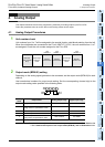
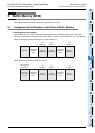
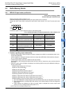
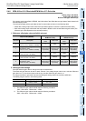
A
Common Items
B
FX
3U
-4AD
FX
3UC
-4AD
C
FX
3U
-4AD-ADP
D
FX
3G
-2AD-BD
E
FX
3U
-4DA
F
FX
3U
-4DA-ADP
G
FX
3G
-1DA-BD
H
FX
3U
-3A-ADP
I
FX
3U
-4AD-PT
-ADP
J
FX
3U
-4AD-PTW
-ADP
FX
3G
/FX
3U
/FX
3UC
PLC User's Manual - Analog Control Edition
FX3U-4DA (4-channel Analog Output)
5.4 Buffer Memory Details
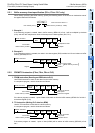
5.4.1 BFM #0: Output mode specification
Initial value (at delivery): H0000
Numeric data type: Hexadecimal (H)
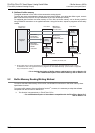
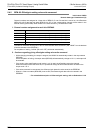
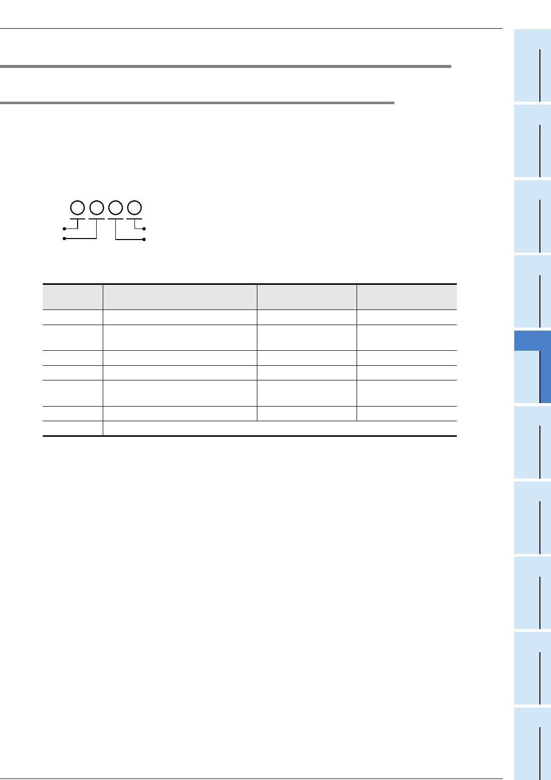
Specify the output modes of channel 1 to 4.
4 hexadecimal digits are assigned to specify the output modes of the 4 channels.
Change the value of each digit to change the output mode of each channel. 0 to 4 and F can be set for each
digit.
The different types of output modes are shown in the following table:
→ For a detailed description of output characteristics, refer to Section 2.4.
*1. The offset/gain values cannot be changed.
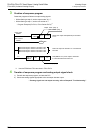
1. Cautions regarding output mode setting
• While the output mode is being changed, the output is stopped, and H0000 is automatically written in the
output status (BFM #6).
At the completion of change of the output mode, the output status (BFM #6) will automatically change to
H1111, and the output is restarted.
• It takes approximately 5 seconds to determine the output mode.
For this reason, after changing the output mode, be sure to wait for 5 seconds or more, and then write the
other data.
• When the output mode is changed, the settings in the following buffer memory are initialized according to
the new output mode.
BFM #5 (output setting upon PLC stop)
*1
BFM #10 to #13 (offset data)
*2
BFM #14 to #17 (gain data)
*2
BFM #28 (disconnection detection status)
*3
BFM #32 to #35 (output data upon PLC stop)
*2
BFM #38 (upper/lower limit function setting)
*1
BFM #41 to #44 (lower limit values of upper/lower limit function)
*2
BFM #45 to #48 (upper limit values of upper/lower limit function)
*2
BFM #50 (Setting of output corrective function by load resistance)
*1
*1
FX
3U
-4DA initializes the corresponding bit to the channel where the user has changed the output mode.
*2
FX
3U
-4DA initializes the corresponding buffer memory to the channel where the user has changed the
output mode.
*3 These settings are initialized only when the output mode is changed from current output mode
(mode 2, 3 or 4) to voltage output mode (mode 0 or 1).
• HFFFF (use of no channels) cannot be set.
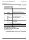
Set value
[HEX]
Output mode Analog output range Digital input range
0 Voltage output mode -10V to +10V -32000 to +32000
1
*1
Voltage output
analog value mV specification mode
-10V to +10V -10000 to +10000
2 Current output mode 0mA to 20mA 0 to 32000
3 Current output mode 4mA to 20mA 0 to 32000
4
*1
Current output
analog value μA specification mode
0mA to 20mA 0 to 20000
5 to E Invalid (setting values unchanged) - -
F Channel not used
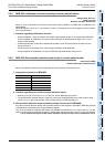
H
ch4
ch3
ch2
ch1