


DS1/T1 CPE loopback jack
Issue 9.1 June 2006 421
Administering a loopback jack
To administer a loopback jack
1. At the management terminal, type change ds1 location
where location is the DS1 interface circuit pack corresponding to the loopback jack.
2. Verify that the near-end CSU type is set to integrated.
3. On page 2 of the form, change the supply CPE loopback jack power field to y.
Setting this field to y informs the technician that a loopback jack is present on the facility
and allows the technician to determine that the facility is available for remote testing.
4. Enter save translation to save the new information.
Testing a loopback jack with a smart jack
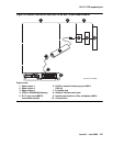
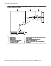
The loopback jack and smart jack isolate faults by dividing the DS1 span into three sections
(see Figure 39
through Figure 41).
These three sections are:
● From the MM710 to the loopback jack
● From the loopback jack to the smart jack (network interface point)
● From the smart jack to the CO
The first two sections are your responsibility. The last is the responsibility of the DS1 service
provider.
Testing the DS1 span from the ICSU to the loopback jack
The DS1 span test has 2 parts:
● Checking for circuit connectivity
The first part of the test powers-up the loopback jack and sends a signal from the DS1
circuit pack, through the wiring, to the loopback jack. The test allows about 10 seconds for
the signal to loop around the loopback jack and return to the DS1 circuit pack. Then it sends
the results to the management terminal and proceeds to the second part of the test.
● The second part of the test sends the standard, 3-in-24 DS1 stress-testing pattern from the
DS1 board, through the loopback jack, and back to a bit error detector and counter on the
DS1 board. A bit-error rate counter displays the results on the management terminal until
you terminate the test.
Always perform both parts of the test. Proceed as follows.