


100 Programmer’s Reference Manual
AC ’97 Modem Controller Registers (D30:F3)
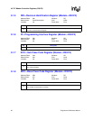
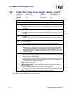
3.2.1 x_BDBAR—Buffer Descriptor List Base Address Register
(Modem—D30:F3)
I/O Address: MBAR + 00h (MIBDBAR), Attribute: R/W
MBAR + 10h (MOBDBAR)
Default Value: 00000000h Size: 32bits
Lockable: No Power Well: Core
Software can read the register at offset 00h by performing a single, 32-bit read from address offset
00h. Reads across DWord boundaries are not supported.
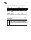
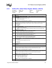
3.2.2 x_CIV—Current Index Value Register (Modem—D30:F3)
I/O Address: MBAR + 04h (MICIV), Attribute: RO
MBAR + 14h (MOCIV),
Default Value: 00h Size: 8bits
Lockable: No Power Well: Core
Software can read the registers at offsets 04h, 05h and 06h simultaneously by performing a single,
32-bit read from address offset 04h. Software can also read this register individually by doing a
single, 8-bit read to offset 04h. Reads across DWord boundaries are not supported.
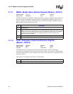
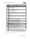
3.2.3 x_LVI—Last Valid Index Register (Modem—D30:F3)
I/O Address: MBAR + 05h (MILVI), Attribute: R/W
MBAR + 15h (MOLVI)
Default Value: 00h Power Well: Core
Software can read the registers at offsets 04h, 05h and 06h simultaneously by performing a single,
32-bit read from address offset 04h. Software can also read this register individually by doing a
single, 8-bit read to offset 05h. Reads across DWord boundaries are not supported.
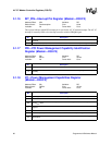
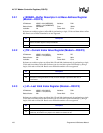
Bit Description
31:3
Buffer Descriptor List Base Address [31:3] — R/W. These bits represent address bits 31:3. The
entries should be aligned on 8-byte boundaries.
2:0 Hardwired to 0.
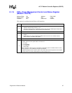
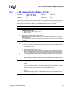
Bit Description
7:5 Hardwired to 0.
4:0
Current Index Value [4:0] — RO. These bits represent which buffer descriptor within the list of 16
descriptors is being processed currently. As each descriptor is processed, this value is
incremented.
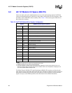
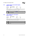
Bit Description
7:5 Hardwired to 0
4:0
Last Valid Index [4:0] — R/W. These bits indicate the last valid descriptor in the list. This value is
updated by the software as it prepares new buffers and adds to the list.