


72 Programmer’s Reference Manual
AC ’97 Audio Controller Registers (D30:F2)
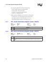
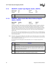
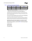
2.1.18 INT_PN—Interrupt Pin Register (Audio—D30:F2)
Address Offset: 3Dh Attribute: RO
Default Value: See Description Size: 8 bits
Lockable: No Power Well: Core
This register indicates which PCI interrupt pin is used for the AC '97 module interrupt. The AC '97
interrupt is internally OR’d to the interrupt controller with the PIRQB# signal.
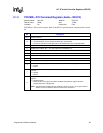
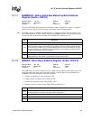
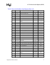
2.1.19 PCID—Programmable Codec Identification Register
(Audio—D30:F2)
Address Offset: 40h Attribute: R/W
Default Value: 09h Size: 8 bits
Lockable: No Power Well: Core
This register is used to specify the ID for the secondary and tertiary codecs for I/O accesses. This
register is not affected by the D3
HOT
to D0 transition. The value in this register must be modified
before any AC ’97 codec accesses.
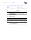
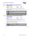
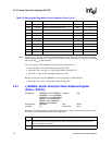
2.1.20 CFG—Configuration Register (Audio—D30:F2)
Address Offset: 41h Attribute: R/W
Default Value: 00h Size: 8 bits
Lockable: No Power Well: Core
This register is used to specify the ID for the secondary and tertiary codecs for I/O accesses. This
register is not affected by the D3
HOT
to D0 transition.
Bit Description
7:0 AC '97 Interrupt Routing — RO. This reflects the value of D30IP.AAIP in chipset configuration space.
Bit Description
7:4 Reserved.
3:2
Tertiary Codec ID (TID) — R/W. These bits define the encoded ID that is used to address the
tertiary codec I/O space. Bit 1 is the first bit sent and Bit 0 is the second bit sent on ACZ_SDOUT
during slot 0.
1:0
Secondary Codec ID (SCID) — R/W. These two bits define the encoded ID that is used to address
the secondary codec I/O space. The two bits are the ID that will be placed on slot 0, bits 0 and 1,
upon an I/O access to the secondary codec. Bit 1 is the first bit sent and bit 0 is the second bit sent
on ACZ_SDOUT during slot 0.
Bit Description
7:1 Reserved—RO.
0
I/O Space Enable (IOSE) — R/W.
0 = Disable. The IOS bit at offset 04h and the I/O space BARs at offset 10h and 14h become read
only registers. Additionally, bit 0 of the I/O BARs at offsets 10h and 14h are hardwired to 0 when
this bit is 0. This is the default state for the I/O BARs. BIOS must explicitly set this bit to allow a
legacy driver to work.
1 = Enable.