


Programmer’s Reference Manual 95
AC ’97 Modem Controller Registers (D30:F3)
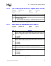
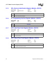
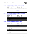
3.1.13 SID—Subsystem Identification Register (Modem—D30:F3)
Address Offset: 2Eh–2Fh Attribute: R/WO
Default Value: 0000h Size: 16 bits
Lockable: No Power Well: Core
The SID register, in combination with the Subsystem Vendor ID register make it possible for the
operating environment to distinguish one audio subsystem from another. This register is
implemented as write-once register. Once a value is written to it, the value can be read back. Any
subsequent writes will have no effect.
This register is not affected by the D3
HOT
to D0 transition.
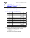
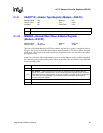
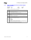
3.1.14 CAP_PTR—Capabilities Pointer Register (Modem—D30:F3)
Address Offset: 34h Attribute: RO
Default Value: 50h Size: 8 bits
Lockable: No Power Well: Core
This register indicates the offset for the capability pointer.
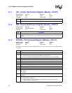
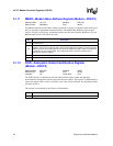
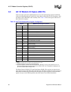
3.1.15 INT_LN—Interrupt Line Register (Modem—D30:F3)
Address Offset: 3Ch Attribute: R/W
Default Value: 00h Size: 8 bits
Lockable: No Power Well: Core
This register indicates which PCI interrupt line is used for the AC ’97 module interrupt.
Bit Description
15:0 Subsystem ID — R/WO.
Bit Description
7:0
Capabilities Pointer (CAP_PTR) — RO. This field indicates that the first capability pointer offset is
offset 50h.
Bit Description
7:0
Interrupt Line (INT_LN) — R/W. This data is not used by the Intel
®
ICH7. It is used to communicate
to software the interrupt line that is connected to the interrupt pin.