


Programmer’s Reference Manual 87
AC ’97 Audio Controller Registers (D30:F2)
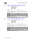
2.2.10 CAS—Codec Access Semaphore Register (Audio—D30:F2)
I/O Address: NABMBAR + 34h Attribute: R/W (special)
Default Value: 00h Size: 8 bits
Lockable: No Power Well: Core
NOTE: Reads across DWord boundaries are not supported.
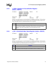
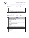
2.2.11 SDM—SDATA_IN Map Register (Audio—D30:F2)
I/O Address: NABMBAR + 80h Attribute: R/W, RO
Default Value: 00h Size: 8 bits
Lockable: No Power Well: Core
NOTE: Reads across DWord boundaries are not supported.
§
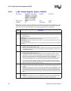
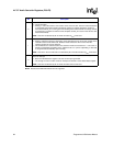
Bit Description
7:1 Reserved.
0
Codec Access Semaphore (CAS) — R/W (special). This bit is read by software to check whether a
codec access is currently in progress.
0 = No access in progress.
1 = The act of reading this register sets this bit to 1. The driver that read this bit can then perform
an I/O access. Once the access is completed, hardware automatically clears this bit.
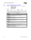
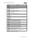
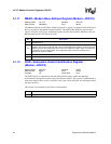
Bit Description
7:6
PCM In 2, Microphone In 2 Data In Line (DI2L)— R/W. When the SE bit is set, these bits indicates
which ACZ_SDIN line should be used by the hardware for decoding the input slots for PCM In 2 and
Microphone In 2. When the SE bit is cleared, the value of these bits are irrelevant, and PCM In 2
and Mic In 2 DMA engines are not available.
00 = ACZ_SDIN0
01 = ACZ_SDIN1
10 = ACZ_SDIN2
11 = Reserved
5:4
PCM In 1, Microphone In 1 Data In Line (DI1L)— R/W. When the SE bit is set, these bits indicates
which ACZ_SDIN line should be used by the hardware for decoding the input slots for PCM In 1 and
Microphone In 1. When the SE bit is cleared, the value of these bits are irrelevant, and the PCM In 1
and Mic In 1 engines use the OR’d ACZ_SDIN lines.
00 = ACZ_SDIN0
01 = ACZ_SDIN1
10 = ACZ_SDIN2
11 = Reserved
3
Steer Enable (SE) — R/W. When set, the ACZ_SDIN lines are treated separately and not OR’d
together before being sent to the DMA engines. When cleared, the ACZ_SDIN lines are OR’d
together, and the “Microphone In 2” and “PCM In 2” DMA engines are not available.
2 Reserved — RO.
1:0
Last Codec Read Data Input (LDI) — RO. When a codec register is read, this indicates which
ACZ_SDIN the read data returned on. Software can use this to determine how the codecs are
mapped. The values are:
00 = ACZ_SDIN0
01 = ACZ_SDIN1
10 = ACZ_SDIN2
11 = Reserved