


Programmer’s Reference Manual 103
AC ’97 Modem Controller Registers (D30:F3)
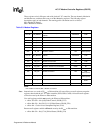
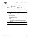
3.2.7 x_CR—Control Register (Modem—D30:F3)
I/O Address: MBAR + 0Bh (MICR), Attribute: R/W, R/W (special)
MBAR + 1Bh (MOCR)
Default Value: 00h Size: 8 bits
Lockable: No Power Well: Core
Software can read the registers at the offsets 08h, 0Ah, and 0Bh by performing a 32-bit read from
the address offset 08h. Software can also read this register individually by doing a single, 8-bit read
to offset 0Bh. Reads across DWord boundaries are not supported.
Bit Description
7:5 Reserved
4
Interrupt on Completion Enable (IOCE) — R/W. This bit controls whether or not an interrupt
occurs when a buffer completes with the IOC bit set in its descriptor.
0 = Disable
1 = Enable
3
FIFO Error Interrupt Enable (FEIE) — R/W. This bit controls whether the occurrence of a FIFO
error will cause an interrupt or not.
0 = Disable. Bit 4 in the Status Register will be set, but the interrupt will not occur.
1 = Enable. Interrupt will occur.
2
Last Valid Buffer Interrupt Enable (LVBIE) — R/W. This bit controls whether the completion of the
last valid buffer will cause an interrupt or not.
0 = Disable. Bit 2 in the Status register will still be set, but the interrupt will not occur.
1 = Enable
1
Reset Registers (RR) — R/W (special).
0 = Removes reset condition.
1 = Contents of all registers to be reset, except the interrupt enable bits (bit 4,3,2 of this register).
Software needs to set this bit. It must be set only when the Run/Pause bit is cleared. Setting it
when the Run bit is set will cause undefined consequences. This bit is self-clearing (software
needs not clear it).
0
Run/Pause Bus Master (RPBM) — R/W.
0 = Pause bus master operation. This results in all state information being retained (i.e., master
mode operation can be stopped and then resumed).
1 = Run. Bus master operation starts.