


56 Programmer’s Reference Manual
Intel
®
High Definition Audio Controller Registers (D27:F0)
Bit Description
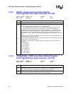
23:20
Stream Number — R/W. This value reflects the Tag associated with the data being transferred on
the link.
When data controlled by this descriptor is sent out over the link, it will have its stream number
encoded on the SYNC signal.
When an input stream is detected on any of the SDI signals that match this value, the data samples
are loaded into FIFO associated with this descriptor.
Note that while a single SDI input may contain data from more than one stream number, two different
SDI inputs may not be configured with the same stream number.
0000 = Reserved
0001 = Stream 1
........
1110 = Stream 14
1111 = Stream 15
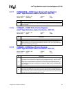
19
Bidirectional Direction Control — RO. This bit is only meaningful for bidirectional streams; therefore,
this bit is hardwired to 0.
18
Traffic Priority — RO. Hardwired to 1 indicating that all streams will use VC1 if it is enabled through
the PCI Express* registers.
17:16 Stripe Control — RO. This bit is only meaningful for input streams; therefore, this bit is hardwired to 0.
15:5 Reserved
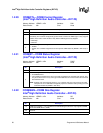
4
Descriptor Error Interrupt Enable — R/W.
0 = Disable
1 = An interrupt is generated when the Descriptor Error Status bit is set.
3
FIFO Error Interrupt Enable — R/W.
0 = Disable.
1 = Enable. This bit controls whether the occurrence of a FIFO error (overrun for input or underrun
for output) will cause an interrupt or not. If this bit is not set, bit 3 in the Status register will be set,
but the interrupt will not occur. Either way, the samples will be dropped.
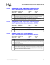
2
Interrupt on Completion Enable — R/W.
0 = Disable.
1 = Enable. This bit controls whether or not an interrupt occurs when a buffer completes with the
IOC bit set in its descriptor. If this bit is not set, bit 2 in the Status register will be set, but the
interrupt will not occur.
1
Stream Run (RUN) — R/W.
0 = Disable. The DMA engine associated with this input stream will be disabled. The hardware will
report a 0 in this bit when the DMA engine is actually stopped. Software must read a 0 from this
bit before modifying related control registers or restarting the DMA engine.
1 = Enable. The DMA engine associated with this input stream will be enabled to transfer data from
the FIFO to the main memory. The SSYNC bit must also be cleared in order for the DMA engine
to run. For output streams, the cadence generator is reset whenever the RUN bit is set.
0
Stream Reset (SRST) — R/W.
0 = Writing a 0 causes the corresponding stream to exit reset. When the stream hardware is ready
to begin operation, it will report a 0 in this bit. Software must read a 0 from this bit before
accessing any of the stream registers.
1 = Writing a 1 causes the corresponding stream to be reset. The Stream Descriptor registers
(except the SRST bit itself) and FIFO’s for the corresponding stream are reset. After the stream
hardware has completed sequencing into the reset state, it will report a 1 in this bit. Software
must read a 1 from this bit to verify that the stream is in reset. The RUN bit must be cleared
before SRST is asserted.