


Programmer’s Reference Manual 55
Intel
®
High Definition Audio Controller Registers (D27:F0)
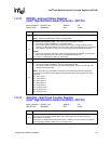
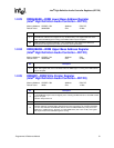
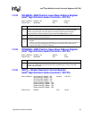
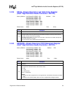
1.2.33 DPLBASE—DMA Position Lower Base Address Register
(Intel
®
High Definition Audio Controller—D27:F0)
Memory Address: HDBAR + 70h Attribute: R/W, RO
Default Value: 00000000h Size: 32 bits
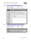
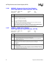
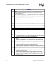
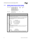
1.2.34 DPUBASE—DMA Position Upper Base Address Register
(Intel
®
High Definition Audio Controller—D27:F0)
Memory Address: HDBAR + 74h Attribute: R/W
Default Value: 00000000h Size: 32 bits
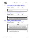
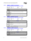
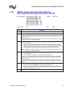
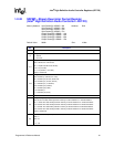
1.2.35 SDCTL—Stream Descriptor Control Register
(Intel
®
High Definition Audio Controller—D27:F0)
Memory Address: Input Stream[0]: HDBAR + 80h Attribute: R/W, RO
Input Stream[1]: HDBAR + A0h
Input Stream[2]: HDBAR + C0h
Input Stream[3]: HDBAR + E0h
Output Stream[0]: HDBAR + 100h
Output Stream[1]: HDBAR + 120h
Output Stream[2]: HDBAR + 140h
Output Stream[3]: HDBAR + 160h
Default Value: 040000h Size: 24 bits
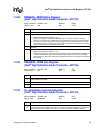
Bit Description
31:7
DMA Position Lower Base Address — R/W. Lower 32 bits of the DMA Position Buffer Base
Address. This register field must not be written when any DMA engine is running or the DMA
transfer may be corrupted. This same address is used by the Flush Control and must be
programmed with a valid value before the Flush Control bit (HDBAR+08h:bit 1) is set.
6:1
DMA Position Lower Base Unimplemented bits — RO. Hardwired to 0 to force the 128-byte buffer
alignment for cache line write optimizations.
0
DMA Position Buffer Enable — R/W.
0 = Disable.
1 = Enable. The controller will write the DMA positions of each of the DMA engines to the buffer in
the main memory periodically (typically once per frame). Software can use this value to
determine what data in memory is valid data.
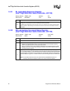
Bit Description
31:0
DMA Position Upper Base Address — R/W. Upper 32 bits of the DMA Position Buffer Base
Address. This register field must not be written when any DMA engine is running or the DMA
transfer may be corrupted.