


42 Programmer’s Reference Manual
Intel
®
High Definition Audio Controller Registers (D27:F0)
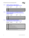
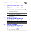
1.2.6 GCTL—Global Control Register
(Intel
®
High Definition Audio Controller—D27:F0)
Memory Address: HDBAR + 08h Attribute: R/W
Default Value: 00000000h Size: 32 bits
Bit Description
31:9 Reserved.
8
Accept Unsolicited Response Enable — R/W.
0 = Unsolicited responses from the codecs are not accepted.
1 = Unsolicited response from the codecs are accepted by the controller and placed into the
Response Input Ring Buffer.
7:2 Reserved.
1
Flush Control — R/W.
0 = Flush Not in progress.
1 = Writing a 1 to this bit initiates a flush. When the flush completion is received by the controller,
hardware sets the Flush Status bit and clears this Flush Control bit. Before a flush cycle is
initiated, the DMA Position Buffer must be programmed with a valid memory address by
software, but the DMA Position Buffer bit 0 needs not be set to enable the position reporting
mechanism. Also, all streams must be stopped (the associated RUN bit must be 0).
When the flush is initiated, the controller will flush the pipelines to memory to ensure that the
hardware is ready to transition to a D3 state. Setting this bit is not a critical step in the power state
transition if the content of the FIFIOs is not critical.
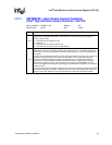
0
Controller Reset # — R/W.
0 = Writing a 0 to this bit causes the Intel
®
High Definition Audio controller to be reset. All state
machines, FIFOs, and non-resume well memory mapped configuration registers (not PCI
configuration registers) in the controller will be reset. The Intel High Definition Audio link
RESET# signal will be asserted, and all other link signals will be driven to their default values.
After the hardware has completed sequencing into the reset state, it will report a 0 in this bit.
Software must read a 0 from this bit to verify the controller is in reset.
1 = Writing a 1 to this bit causes the controller to exit its reset state and deassert the Intel High
Definition Audio link RESET# signal. Software is responsible for setting/clearing this bit such
that the minimum Intel High Definition Audio link RESET# signal assertion pulse width
specification is met. When the controller hardware is ready to begin operation, it will report a 1
in this bit. Software must read a 1 from this bit before accessing any controller registers. This
bit defaults to a 0 after Hardware reset, therefore, software needs to write a 1 to this bit to
begin operation.
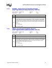
NOTES:
1. The CORB/RIRB RUN bits and all stream RUN bits must be verified cleared to 0 before writing
a 0 to this bit in order to assure a clean re-start.
2. When setting or clearing this bit, software must ensure that minimum link timing requirements
(minimum RESET# assertion time, etc.) are met.
3. When this bit is 0 indicating that the controller is in reset, writes to all Intel High Definition Audio
memory mapped registers are ignored as if the device is not present. The only exception is this
register itself. The Global Control register is write-able as a DWord, Word, or Byte even when
CRST# (this bit) is 0 if the byte enable for the byte containing the CRST# bit (Byte Enable 0) is
active. If Byte Enable 0 is not active, writes to the Global Control register will be ignored when
CRST# is 0. When CRST# is 0, reads to Intel High Definition Audio memory mapped registers
will return their default value except for registers that are not reset with PLTRST# or on a
D3
HOT
to D0 transition.