


Programmer’s Reference Manual 47
Intel
®
High Definition Audio Controller Registers (D27:F0)
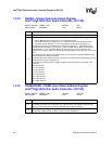
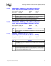
1.2.13 INTSTS—Interrupt Status Register
(Intel
®
High Definition Audio Controller—D27:F0)
Memory Address: HDBAR + 24h Attribute: RO
Default Value: 00000000h Size: 32 bits
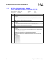
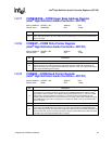
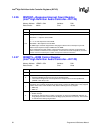
1.2.14 WALCLK—Wall Clock Counter Register
(Intel
®
High Definition Audio Controller—D27:F0)
Memory Address: HDBAR + 30h Attribute: RO
Default Value: 00000000h Size: 32 bits
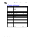
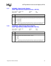
Bit Description
31
Global Interrupt Status (GIS) — RO. This bit is an OR of all the interrupt status bits in this register.
NOTE: This bit is not affected by the D3
HOT
to D0 transition.
30
Controller Interrupt Status (CIS) — RO. Status of general controller interrupt.
0 = An interrupt condition did Not occur as described below.
1 = An interrupt condition occurred due to a Response Interrupt, a Response Buffer Overrun
Interrupt, or a SDIN State Change event. The exact cause can be determined by interrogating
other registers. This bit is an OR of all of the stated interrupt status bits for this register.
NOTES:
1. This bit is set regardless of the state of the corresponding interrupt enable bit, but a hardware
interrupt will not be generated unless the corresponding enable bit is set.
2. This bit is not affected by the D3
HOT
to D0 transition.
29:8 Reserved
7:0
Stream Interrupt Status (SIS) — RO.
0 = An interrupt condition did Not occur on the corresponding stream.
1 = An interrupt condition occurred on the corresponding stream. This bit is an OR of all of the
stream’s interrupt status bits.
NOTE: These bits are set regardless of the state of the corresponding interrupt enable bits.
The streams are numbered and the SIE bits assigned sequentially, based on their order in the
register set.
Bit 0: input stream 1
Bit 1: input stream 2
Bit 2: input stream 3
Bit 3: input stream 4
Bit 4: output stream 1
Bit 5: output stream 2
Bit 6: output stream 3
Bit 7: output stream 4
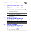
Bit Description
31:0
Wall Clock Counter — RO. This 32-bit counter field is incremented on each link BCLK period and
rolls over from FFFF FFFFh to 0000 0000h. This counter will roll over to 0 with a period of
approximately 179 seconds.
This counter is enabled while the BCLK bit is set to 1. Software uses this counter to synchronize
between multiple controllers. Will be reset on controller reset.