


Programmer’s Reference Manual 91
AC ’97 Modem Controller Registers (D30:F3)
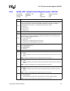
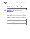
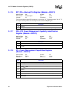
3.1.4 PCISTS—PCI Status Register (Modem—D30:F3)
Address Offset: 06h–07h Attribute: R/WC, RO
Default Value: 0290h Size: 16 bits
Lockable: No Power Well: Core
PCISTS is a 16-bit status register. Refer to the PCI Local Bus Specification for complete details on
each bit.
Note: For the writable bits, software must write a 1 to clear bits that are set. Writing a 0 to the bit has no
effect.
Bit Description
15 Detected Parity Error (DPE) — RO. Not implemented. Hardwired to 0.
14 Signaled System Error (SSE) —RO. Not implemented. Hardwired to 0.
13
Master Abort Status (MAS) — R/WC.
0 = Master abort Not generated by bus master AC ‘97 function.
1 = Bus Master AC ‘97 interface function, as a master, generates a master abort.
12 Reserved. Read as 0.
11 Signaled Target Abort (STA) — RO. Not implemented. Hardwired to 0.
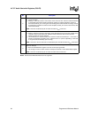
10:9
DEVSEL# Timing Status (DEV_STS) — RO. This 2-bit field reflects the ICH7's DEVSEL# timing
parameter. These read only bits indicate the ICH7's DEVSEL# timing when performing a positive
decode.
8 Data Parity Error Detected (DPED) — RO. Not implemented. Hardwired to 0.
7
Fast Back to Back Capable (FB2BC) — RO. Hardwired to 1. This bit indicates that the ICH7 as a
target is capable of fast back-to-back transactions.
6 User Definable Features (UDF) — RO. Not implemented. Hardwired to 0.
5 66 MHz Capable (66MHZ_CAP) — RO. Hardwired to 0.
4
Capabilities List (CAP_LIST) — RO. Indicates that the controller contains a capabilities pointer list.
The first item is pointed to by looking at configuration offset 34h.
3
Interrupt Status (INTS) — RO.
0 = This bit is 0 after the interrupt is cleared.
1 = This bit is 1 when the INTx# is asserted.
2:0 Reserved