


26 Programmer’s Reference Manual
Intel
®
High Definition Audio Controller Registers (D27:F0)
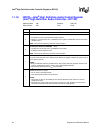
1.1.25 MID—MSI Capability ID Register
(Intel
®
High Definition Audio Controller—D27:F0)
Address Offset: 60h–61h Attribute: RO
Default Value: 7005h Size: 16 bits
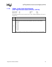
1.1.26 MMC—MSI Message Control Register
(Intel
®
High Definition Audio Controller—D27:F0)
Address Offset: 62h–63h Attribute: RO, R/W
Default Value: 0080h Size: 16 bits
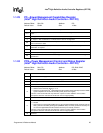
1:0
Power State (PS) — R/W. This field is used both to determine the current power state of the Intel
High Definition Audio controller and to set a new power state.
00 = D0 state
11 = D3
HOT
state
Others = reserved
NOTES:
1. If software attempts to write a value of 01b or 10b in to this field, the write operation must
complete normally; however, the data is discarded and no state change occurs.
2. When in the D3
HOT
states, the Intel High Definition Audio controller’s configuration space is
available, but the I/O and memory space are not. Additionally, interrupts are blocked.
3. When software changes this value from D3
HOT
state to the D0 state, an internal warm (soft) reset
is generated, and software must re-initialize the function.
Bit Description
Bit Description
15:8 Next Capability (Next) — RO. Hardwired to 70h. Points to the PCI Express* capability structure.
7:0 Cap ID (CAP) — RO. Hardwired to 05h. Indicates that this pointer is a MSI capability
Bit Description
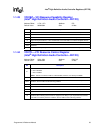
15:8 Reserved
7
64b Address Capability (64ADD) — RO. Hardwired to 1 indicating the ability to generate a 64-bit
message address
6:4
Multiple Message Enable (MME) — RO. Normally this is a R/W register. However, since only 1
message is supported, these bits are hardwired to 000 = 1 message.
3:1 Multiple Message Capable (MMC) — RO. Hardwired to 0 indicating request for 1 message.
0
MSI Enable (ME) — R/W.
0 = an MSI may not be generated
1 = an MSI will be generated instead of an INTx signal.