


116 Programmer’s Reference Manual
Intel® High Definition Audio BIOS Considerations
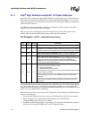
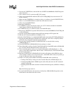
4.1.2.3 Codec Initialization Programming Sequence
After BIOS has determined the presence of Intel® HD Audio codec(s), it must follow the
programming sequence given in this section to update the codec with correct jack information
specific to the platform for Intel® HD Audio driver to retrieve and use later.
There are two ways for software to send verbs to and receive response data from codecs over the
Intel® HD Audio codec link: Using CORB/RIRB (Command Output Ring Buffer / Response Input
Ring Buffer), or using Immediate Command/Immediate Response register pair. The sequence
below uses the latter which does not require the availability of a memory buffer.
BIOS should ensure that the Intel® HD Audio AZBAR at PCI config space 10h-17h contains a
valid address value and is enabled by setting PCI command register 04h[1]=1. BIOS should also
ensure that the Controller Reset# bit of Global Control register in memory-mapped space
(AZBAR+08h[0]) is set to 1 and read back as 1.
For each Intel® HD Audio codec present as indicated by AZBAR+0Eh[2:0], BIOS should perform
the codec initialization as described below:
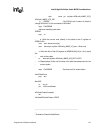
1. Read the VenderID/DeviceID pair from the attached codec
• Poll the ICB bit of IRS register at AZBAR+68h[0] to make sure it returns 0.
• Write verb c00F0000h (dword) to the IC register at AZBAR+60h, where: ‘c’ (bits
31:28) represents the codec address (CAd).
• Write the bits of IRS register at AZBAR+68h[1:0] to 11b to send the verb to codec.
• Poll IRS register bits at AZBAR+68h[1:0] until it returns 10b indicating the verb has
been sent to the codec and response data from codec is now valid.
• Read the IR register at AZBAR+64h, the dword data is the VID/DID value returned by
the codec.
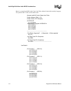
2. Check against internal list to determine if there is a stored verb table which matches the CAd/
VID/DID information.
Note that steps 1 and 2 are BIOS implementation-specific steps and can be done in different
ways. If a BIOS has prior knowledge of fixed platform/codec combination (e.g., for a BIOS
having 3 stored verb tables for 3 known codecs at known codec addresses on a known
platform), a simple pre-defined codec-to-table matching can be used and steps 1 and 2 can be
eliminated. For a BIOS to support multiple codec/platform combinations, an internal match-
list might be needed to match a platform/codec combination to a codec verb table.
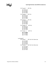
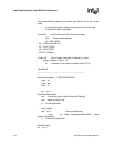
3. If there is a match, send the entire list of verbs in the matching verb table one by one to the
codec.
• Poll the ICB bit of IRS register at AZBAR+68h[0] to make sure it returns 0.
• Write the next verb (dword) in the table to the IC register at AZBAR+60h,
• Write the bits of IRS register at AZBAR+68h[1:0] to 11b to send the verb to codec.
• Poll the ICB bit of IRS register at AZBAR+68h[0] until it returns 0 indicating the verb has
been sent to the codec.
• Repeat the steps until all the verbs in the table have been sent.
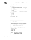
Note: Some verbs in the table may need to be qualified by certain platform-specific conditions. For
example, for the sample table above, the verbs for Pin Complex 7 and 8 (NID=14,16 respectively)
should be sent only if the Front Panel Jacks are present and connected on the platform, which may
be indicated by a software flag that is controlled by certain GPIO pin state.