


Programmer’s Reference Manual 43
Intel
®
High Definition Audio Controller Registers (D27:F0)
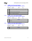
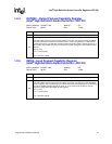
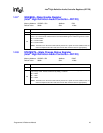
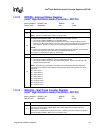
1.2.7 WAKEEN—Wake Enable Register
(Intel
®
High Definition Audio Controller—D27:F0)
Memory Address: HDBAR + 0Ch Attribute: R/W
Default Value: 0000h Size: 16 bits
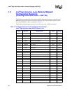
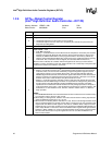
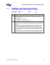
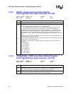
1.2.8 STATESTS—State Change Status Register
(Intel
®
High Definition Audio Controller—D27:F0)
Memory Address: HDBAR + 0Eh Attribute: R/WC
Default Value: 0000h Size: 16 bits
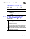
Bit Description
15:3 Reserved.
2:0
SDIN Wake Enable Flags — R/W. These bits control which SDI signal(s) may generate a wake
event. A 1b in the bit mask indicates that the associated SDIN signal is enabled to generate a wake.
Bit 0 is used for SDI0
Bit 1 is used for SDI1
Bit 2 is used for SDI2
NOTE: These bits are in the resume well and only cleared on a power on reset. Software must not
make assumptions about the reset state of these bits and must set them appropriately.
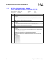
Bit Description
15:3 Reserved.
2:0
SDIN State Change Status Flags — R/WC. Flag bits that indicate which SDI signal(s) received a
state change event. The bits are cleared by writing 1’s to them.
Bit 0 = SDI0
Bit 1 = SDI1
Bit 2 = SDI2
NOTE: These bits are in the resume well and only cleared on a power on reset. Software must not
make assumptions about the reset state of these bits and must set them appropriately.