


106 Programmer’s Reference Manual
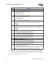
AC ’97 Modem Controller Registers (D30:F3)
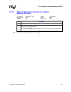
Note: On reads from a codec, the controller will give the codec a maximum of four frames to respond,
after which if no response is received, it will return a dummy read completion to the processor
(with all F’s on the data) and also set the Read Completion Status bit in the Global Status Register.
Note: Reads across DWord boundaries are not supported.
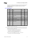
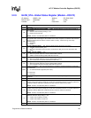
13 Bit 2 of Slot 12 — RO. Display bit 2 of the most recent slot 12.
12 Bit 1 of Slot 12 — RO. Display bit 1 of the most recent slot 12.
11
ACZ_SDIN1 Resume Interrupt (S1RI) — R/WC. This bit indicates that a resume event occurred on
ACZ_SDIN1. Software clears this bit by writing a 1 to it.
0 = Resume event did Not occur.
1 = Resume event occurred.
NOTE: This bit is not affected by D3
HOT
to D0 Reset.
10
ACZ_SDIN0 Resume Interrupt (S0RI) — R/WC. This bit indicates that a resume event occurred on
ACZ_SDIN0. Software clears this bit by writing a 1 to it.
0 = Resume event did Not occur.
1 = Resume event occurred.
NOTE: This bit is not affected by D3
HOT
to D0 Reset.
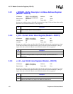
9
ACZ_SDIN1 Codec Ready (S1CR) — RO. This bit reflects the state of the codec ready bit in
ACZ_SDIN1. Bus masters ignore the condition of the codec ready bits, so software must check this
bit before starting the bus masters. Once the codec is “ready”, it must never go “not ready”
spontaneously.
0 = Not Ready.
1 = Ready.
8
ACZ_SDIN0 Codec Ready (S0CR) — RO. This bit reflects the state of the codec ready bit in
ACZ_SDIN 0. Bus masters ignore the condition of the codec ready bits, so software must check this
bit before starting the bus masters. Once the codec is “ready”, it must never go “not ready”
spontaneously.
0 = Not Ready.
1 = Ready.
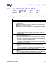
7
Microphone In Interrupt (MINT) — RO.
0 = When the specific status bit is cleared, this bit will be cleared.
1 = One of the Mic in channel interrupts status bits has been set.
6
PCM Out Interrupt (POINT) — RO.
0 = When the specific status bit is cleared, this bit will be cleared.
1 = One of the PCM out channel interrupts status bits has been set.
5
PCM In Interrupt (PIINT) — RO.
0 = When the specific status bit is cleared, this bit will be cleared.
1 = One of the PCM in channel interrupts status bits has been set.
4:3 Reserved
2
Modem Out Interrupt (MOINT) — RO.
0 = When the specific status bit is cleared, this bit will be cleared.
1 = One of the modem out channel interrupts status bits has been set.
1
Modem In Interrupt (MIINT) — RO.
0 = When the specific status bit is cleared, this bit will be cleared.
1 = One of the modem in channel interrupts status bits has been set.
0
GPI Status Change Interrupt (GSCI) — R/WC.
0 = Software clears this bit by writing a 1 to it.
1 = This bit reflects the state of bit 0 in slot 12, and is set when bit 0 of slot 12 is set. This indicates
that one of the GPI’s changed state, and that the new values are available in slot 12.
NOTE: This bit has not affected by AC ‘97 Audio Modem function D3
HOT
to D0 Reset.
Bit Description