


Programmer’s Reference Manual 105
AC ’97 Modem Controller Registers (D30:F3)
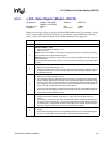
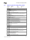
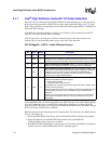
3.2.9 GLOB_STA—Global Status Register (Modem—D30:F3)
I/O Address: MBAR + 40h Attribute: RO, R/W, R/WC
Default Value: 00300000h Size: 32 bits
Lockable: No Power Well: Core
Bit Description
31:30 Reserved.
29
ACZ_SDIN2 Resume Interrupt (S2RI)
— R/WC. This bit indicates a resume event occurred on
ACZ_SDIN2.
0 = Software clears this bit by writing a 1 to it.
1 = Resume event occurred.
NOTE: This bit is not affected by D3
HOT
to D0 Reset.
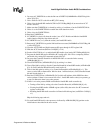
28
ACZ_SDIN2 Codec Ready (S2CR)
— RO. This bit reflects the state of the codec ready bit on
ACZ_SDIN2. Bus masters ignore the condition of the codec ready bits, so software must check this
bit before starting the bus masters. Once the codec is “ready”, it must never go “not ready”
spontaneously.
0 = Not Ready.
1 = Ready.
27
Bit Clock Stopped (BCS)
— RO. This bit indicates that the bit clock is not running.
0 = Transition is found on BIT_CLK.
1 = Intel
®
ICH7 detects that there has been no transition on BIT_CLK for four consecutive PCI
clocks.
26
S/PDIF* Interrupt (SPINT)
— RO.
0 = When the specific status bit is cleared, this bit will be cleared.
1 = S/PDIF out channel interrupt status bits have been set.
25
PCM In 2 Interrupt (P2INT)
— RO.
0 = When the specific status bit is cleared, this bit will be cleared.
1 = One of the PCM In 2 channel status bits have been set.
24
Microphone 2 In Interrupt (M2INT)
— RO.
0 = When the specific status bit is cleared, this bit will be cleared.
1 = One of the Mic in channel interrupts status bits has been set.
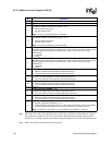
23:22
Sample Capabilities
— RO. This field indicates the capability to support greater than 16-bit audio.
00 = Reserved
01 = 16 and 20-bit Audio supported (ICH7 value)
10 = Reserved
11 = Reserved
21:20
Multichannel Capabilities
— RO. This field indicates the capability to support 4 and 6 channels on
PCM Out.
19:18 Reserved.
17
MD3 — R/W. Power down semaphore for Modem. This bit exists in the suspend well and maintains
context across power states (except G3). The bit has no hardware function. It is used by software in
conjunction with the AD3 bit to coordinate the entry of the two codecs into D3 state.
NOTE: This bit is not affected by D3
HOT
to D0 Reset.
16
AD3 — R/W. Power down semaphore for Audio. This bit exists in the suspend well and maintains
context across power states (except G3). The bit has no hardware function. It is used by software in
conjunction with the MD3 bit to coordinate the entry of the two codecs into D3 state.
NOTE: This bit is not affected by D3
HOT
to D0 Reset.
15
Read Completion Status (RCS)
— R/WC. This bit indicates the status of codec read completions.
Software clears this bit by writing a 1 to it.
0 = A codec read completes normally.
1 = A codec read results in a time-out.
NOTE: This bit is not affected by D3
HOT
to D0 Reset.
14 Bit 3 of Slot 12 — RO. Display bit 3 of the most recent slot 12.