


Programmer’s Reference Manual 83
AC ’97 Audio Controller Registers (D30:F2)
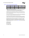
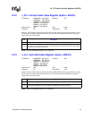
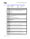
2.2.8 GLOB_CNT—Global Control Register (Audio—D30:F2)
I/O Address: NABMBAR + 2Ch Attribute: R/W, R/W (special)
Default Value: 00000000h Size: 32 bits
Lockable: No Power Well: Core
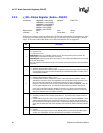
Bit Description
31:30
S/PDIF Slot Map (SSM) — R/W. If the run/pause bus master bit (bit 0 of offset 2Bh) is set, then the
value in these bits indicate which slots S/PDIF data is transmitted on. Software must ensure that the
programming here does not conflict with the PCM channels being used. If there is a conflict,
unpredictable behavior will result — the hardware will not check for a conflict.
00 = Reserved
01 = Slots 7 and 8
10 = Slots 6 and 9
11 = Slots 10 and 11
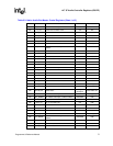
29:24 Reserved.
23:22
PCM Out Mode (POM) — R/W. Enables the PCM out channel to use 16- or 20-bit audio on PCM
out. This does not affect the microphone of S/PDIF DMA. When greater than 16-bit audio is used,
the data structures are aligned as 32-bits per sample, with the highest order bits representing the
data, and the lower order bits as don’t care.
00 = 16 bit audio (default)
01 = 20 bit audio
10 = Reserved. If set, indeterminate behavior will result.
11 = Reserved. If set, indeterminate behavior will result.
21:20
PCM 4/6 Enable — R/W. This field configures PCM Output for 2-, 4- or 6-channel mode.
00 = 2-channel mode (default)
01 = 4-channel mode
10 = 6-channel mode
11 = Reserved
19:7 Reserved.
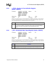
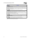
6
ACZ_SDIN2 Interrupt Enable — R/W.
0 = Disable.
1 = Enable an interrupt to occur when the codec on the ACZ_SDIN2 causes a resume event on the
AC-link.
NOTE: This bit is not affected by AC ‘97 Audio Function D3
HOT
to D0 reset.
5
ACZ_SDIN1 Interrupt Enable — R/W.
0 = Disable.
1 = Enable an interrupt to occur when the codec on the ACZ_SDIN1 causes a resume event on the
AC-link.
NOTE: This bit is not affected by AC ‘97 Audio Function D3
HOT
to D0 reset.
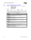
4
ACZ_SDIN0 Interrupt Enable — R/W.
0 = Disable.
1 = Enable an interrupt to occur when the codec on ACZ_SDIN0 causes a resume event on the
AC-link.
NOTE: This bit is not affected by AC ‘97 Audio Function D3
HOT
to D0 reset.
3
AC-LINK Shut Off (LSO) — R/W.
0 = Normal operation.
1 = Controller disables all outputs which will be pulled low by internal pull down resistors.
NOTE: This bit is not affected by AC ‘97 Audio Function D3
HOT
to D0 reset.