


46 Programmer’s Reference Manual
Intel
®
High Definition Audio Controller Registers (D27:F0)
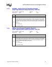
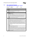
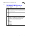
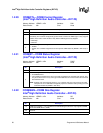
1.2.12 INTCTL—Interrupt Control Register
(Intel
®
High Definition Audio Controller—D27:F0)
Memory Address: HDBAR + 20h Attribute: R/W
Default Value: 00000000h Size: 32 bits
Bit Description
31
Global Interrupt Enable (GIE) — R/W. Global bit to enable device interrupt generation.
0 = Disable.
1 = Enable. The Intel
®
High Definition Audio function is enabled to generate an interrupt. This
control is in addition to any bits in the bus specific address space, such as the Interrupt Enable
bit in the PCI configuration space.
NOTE: This bit is not affected by the D3
HOT
to D0 transition.
30
Controller Interrupt Enable (CIE) — R/W. Enables the general interrupt for controller functions.
0 = Disable.
1 = Enable. The controller generates an interrupt when the corresponding status bit gets set due to
a Response Interrupt, a Response Buffer Overrun, and State Change events.
NOTE: This bit is not affected by the D3
HOT
to D0 transition.
29:8 Reserved
7:0
Stream Interrupt Enable (SIE) — R/W.
0 = Disable.
1 = Enable. When set to 1, the individual streams are enabled to generate an interrupt when the
corresponding status bits get set.
A stream interrupt will be caused as a result of a buffer with IOC = 1in the BDL entry being
completed, or as a result of a FIFO error (underrun or overrun) occurring. Control over the
generation of each of these sources is in the associated Stream Descriptor.
The streams are numbered and the SIE bits assigned sequentially, based on their order in the
register set.
Bit 0: input stream 1
Bit 1: input stream 2
Bit 2: input stream 3
Bit 3: input stream 4
Bit 4: output stream 1
Bit 5: output stream 2
Bit 6: output stream 3
Bit 7: output stream 4