


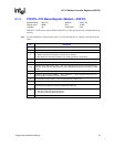

84 Programmer’s Reference Manual
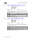
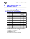
AC ’97 Audio Controller Registers (D30:F2)
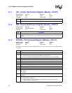
NOTE: Reads across DWord boundaries are not supported.
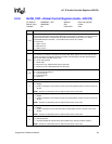
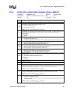
2
AC ’97 Warm Reset — R/W (special).
0 = Normal operation.
1 = Writing a 1 to this bit causes a warm reset to occur on the AC-link. The warm reset will awaken
a suspended codec without clearing its internal registers. If software attempts to perform a
warm reset while bit_clk is running, the write will be ignored and the bit will not change. This bit
is self-clearing (it remains set until the reset completes and bit_clk is seen on the AC-link, after
which it clears itself).
NOTE: This bit is not affected by AC ‘97 Audio Function D3
HOT
to D0 reset.
1
AC ’97 Cold Reset# — R/W.
0 = Writing a 0 to this bit causes a cold reset to occur throughout the AC ‘97 circuitry. All data in the
controller and the codec will be lost. Software needs to clear this bit no sooner than the
minimum number of ms have elapsed.
1 = This bit defaults to 0 and hence after reset, the driver needs to set this bit to a 1. The value of
this bit is retained after suspends; hence, if this bit is set to a 1 prior to suspending, a cold reset
is not generated automatically upon resuming.
NOTE: This bit is in the core well and is not affected by AC ‘97 Audio Function D3
HOT
to D0 reset.
0
GPI Interrupt Enable (GIE) — R/W. This bit controls whether the change in status of any GPI
causes an interrupt.
0 = Bit 0 of the Global Status register is set, but no interrupt is generated.
1 = The change on value of a GPI causes an interrupt and sets bit 0 of the Global Status register.
NOTE: This bit is not affected by AC ‘97 Audio Function D3
HOT
to D0 reset.
Bit Description