


52 Programmer’s Reference Manual
Intel
®
High Definition Audio Controller Registers (D27:F0)
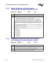
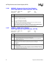
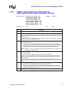
1.2.26 RINTCNT—Response Interrupt Count Register
(Intel
®
High Definition Audio Controller—D27:F0)
Memory Address: HDBAR + 5Ah Attribute: R/W
Default Value: 0000h Size: 16 bits
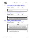
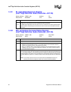
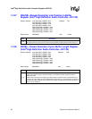
1.2.27 RIRBCTL—RIRB Control Register
(Intel
®
High Definition Audio Controller—D27:F0)
Memory Address: HDBAR + 5Ch Attribute: R/W
Default Value: 00h Size: 8 bits
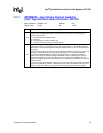
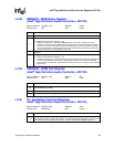
Bit Description
15:8 Reserved.
31:0
N Response Interrupt Count — R/W.
0000 0001b = 1 response sent to RIRB
...........
1111 1111b = 255 responses sent to RIRB
0000 0000b = 256 responses sent to RIRB
The DMA engine should be stopped when changing this field or else an interrupt may be lost.
Note that each response occupies 2 DWords in the RIRB.
This is compared to the total number of responses that have been returned, as opposed to the
number of frames in which there were responses. If more than one codec responds in one frame,
then the count is increased by the number of responses received in the frame.
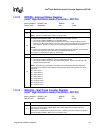
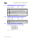
Bit Description
7:3 Reserved.
2
Response Overrun Interrupt Control — R/W.
0 = Hardware will Not generated an interrupt as described below.
1 = The hardware will generate an interrupt when the Response Overrun Interrupt Status bit
(HDBAR + 5Dh: bit 2) is set.
1
Enable RIRB DMA Engine — R/W. After software writes a 0 to this bit, the hardware may not stop
immediately. The hardware will physically update the bit to 0 when the DMA engine is truly stopped.
Software must read a 0 from this bit to verify that the DMA engine is truly stopped.
0 = DMA stop
1 = DMA run
0
Response Interrupt Control — R/W.
0 = Disable Interrupt
1 = Generate an interrupt after N number of responses are sent to the RIRB buffer OR when an
empty Response slot is encountered on all SDI[x] inputs (whichever occurs first). The N counter
is reset when the interrupt is generated.