98 Programmer’s Reference Manual
AC ’97 Modem Controller Registers (D30:F3)
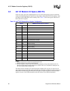
3.2 AC ’97 Modem I/O Space (D30:F3)
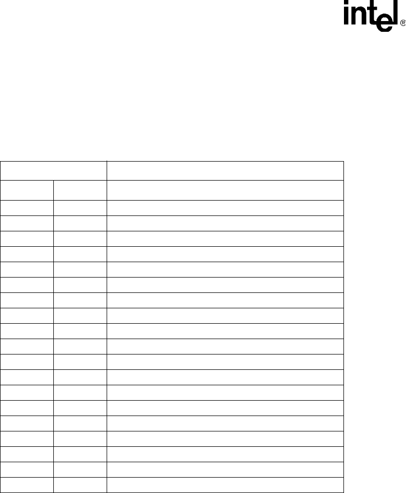
In the case of the split codec implementation accesses to the modem mixer registers in different
codecs are differentiated by the controller by using address offsets 00h
–7Fh for the primary codec
and address offsets 80h
–FEh for the secondary codec. Table 3-2 shows the register addresses for
the modem mixer registers.
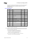
NOTES:
1. Registers in italics are for functions not supported by the ICH7.
2. Software should not try to access reserved registers.
3. The ICH7 supports a modem codec connected to ACZ_SDIN[2:0], as long as the Codec ID is 00 or 01.
However, the ICH7 does not support more than one modem codec. For a complete list of topologies, see
your ICH7 enabled Platform Design Guide.
The Global Control (GLOB_CNT) and Global Status (GLOB_STA) registers are aliased to the
same global registers in the audio and modem I/O space. Therefore a read/write to these registers in
either audio or modem I/O space affects the same physical register. Software could access these
registers as bytes, word, DWord quantities, but reads must not cross DWord boundaries.
Table 3-2. Intel
®
ICH7 Modem Mixer Register Configuration
Register MMBAR Exposed Registers (D30:F3)
Primary Secondary Name
00h:38h 80h:B8h Intel RESERVED
3Ch BCh Extended Modem ID
3Eh BEh Extended Modem Stat/Ctrl
40h C0h Line 1 DAC/ADC Rate
42h C2h Line 2 DAC/ADC Rate
44h C4h Handset DAC/ADC Rate
46h C6h Line 1 DAC/ADC Level Mute
48h C8h Line 2 DAC/ADC Level Mute
4Ah CAh Handset DAC/ADC Level Mute
4Ch CCh GPIO Pin Config
4Eh CEh GPIO Polarity/Type
50h D0h GPIO Pin Sticky
52h D2h GPIO Pin Wake Up
54h D4h GPIO Pin Status
56h D6h Misc. Modem AFE Stat/Ctrl
58h D8h AC ’97 Reserved
5Ah DAh Vendor Reserved
7Ch FCh Vendor ID1
7Eh FEh Vendor ID2


