


80 Programmer’s Reference Manual
AC ’97 Audio Controller Registers (D30:F2)
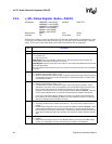
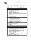
2.2.4 x_SR—Status Register (Audio—D30:F2)
I/O Address: NABMBAR + 06h (PISR), Attribute: R/WC, RO
NABMBAR + 16h (POSR),
NABMBAR + 26h (MCSR)
MBBAR + 46h (MC2SR)
MBBAR + 56h (PI2SR)
MBBAR + 66h (SPSR)
Default Value: 0001h Size: 16 bits
Lockable: No Power Well: Core
Software can read the registers at offsets 04h, 05h and 06h simultaneously by performing a single,
32-bit read from address offset 04h. Software can also read this register individually by doing a
single, 16-bit read to offset 06h. Reads across DWord boundaries are not supported.
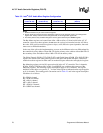
Bit Description
15:5 Reserved.
4
FIFO Error (FIFOE) — R/WC. Software clears this bit by writing a 1 to it.
0 = No FIFO error.
1 = FIFO error occurs.
PISR Register: FIFO error indicates a FIFO overrun. The FIFO pointers don't increment, the
incoming data is not written into the FIFO, thus is lost.
POSR Register: FIFO error indicates a FIFO underrun. The sample transmitted in this case should
be the last valid sample.
The ICH7 will set the FIFO bit if the under-run or overrun occurs when there are more valid buffers
to process.
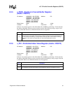
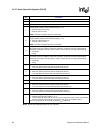
3
Buffer Completion Interrupt Status (BCIS) — R/WC.
0 = Software clears this bit by writing a 1 to it.
1 = Set by the hardware after the last sample of a buffer has been processed, AND if the Interrupt
on Completion (IOC) bit is set in the command byte of the buffer descriptor. It remains active
until cleared by software.
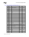
2
Last Valid Buffer Completion Interrupt (LVBCI) — R/WC.
0 = Software clears this bit by writing a 1 to it.
1 = Last valid buffer has been processed. It remains active until cleared by software. This bit
indicates the occurrence of the event signified by the last valid buffer being processed. Thus
this is an event status bit that can be cleared by software once this event has been
recognized. This event will cause an interrupt if the enable bit (D30:F2:NABMBAR + 0Bh, bit
2) in the Control Register is set. The interrupt is cleared when the software clears this bit.
In the case of Transmits (PCM out, Modem out) this bit is set, after the last valid buffer has
been fetched (not after transmitting it). While in the case of Receives, this bit is set after the
data for the last buffer has been written to memory.
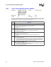
1
Current Equals Last Valid (CELV) — RO.
0 = Cleared by hardware when controller exists state (i.e., until a new value is written to the LVI
register.)
1 = Current Index is equal to the value in the Last Valid Index Register (D30:F2:NABMBAR + 05h),
and the buffer pointed to by the CIV has been processed (i.e., after the last valid buffer has
been processed). This bit is very similar to bit 2, except this bit reflects the state rather than the
event. This bit reflects the state of the controller, and remains set until the controller exits this
state.
0
DMA Controller Halted (DCH) — RO.
0 = Running.
1 = Halted. This could happen because of the Start/Stop bit being cleared and the DMA engines
are idle, or it could happen once the controller has processed the last valid buffer.