Programmer’s Reference Manual 51
Intel
®
High Definition Audio Controller Registers (D27:F0)
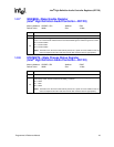
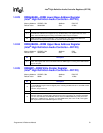
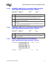
1.2.23 RIRBLBASE—RIRB Lower Base Address Register
(Intel
®
High Definition Audio Controller—D27:F0)
Memory Address: HDBAR + 50h Attribute: R/W, RO
Default Value: 00000000h Size: 32 bits
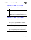
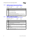
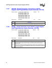
1.2.24 RIRBUBASE—RIRB Upper Base Address Register
(Intel
®
High Definition Audio Controller—D27:F0)
Memory Address: HDBAR + 54h Attribute: R/W
Default Value: 00000000h Size: 32 bits
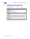
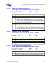
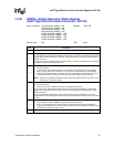
1.2.25 RIRBWP—RIRB Write Pointer Register
(Intel
®
High Definition Audio Controller—D27:F0)
Memory Address: HDBAR + 58h Attribute: R/W, RO
Default Value: 0000h Size: 16 bits
Bit Description
31:7
CORB Lower Base Address — R/W. Lower address of the Response Input Ring Buffer, allowing
the RIRB base address to be assigned on any 128-B boundary. This register field must not be
written when the DMA engine is running or the DMA transfer may be corrupted.
6:0
RIRB Lower Base Unimplemented Bits — RO. Hardwired to 0. This required the RIRB to be
allocated with 128-B granularity to allow for cache line fetch optimizations.
Bit Description
31:0
RIRB Upper Base Address — R/W. Upper 32 bits of the address of the Response Input Ring
Buffer. This register field must not be written when the DMA engine is running or the DMA transfer
may be corrupted.
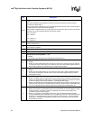
Bit Description
15
RIRB Write Pointer Reset — R/W. Software writes a 1 to this bit to reset the RIRB Write Pointer to
0. The RIRB DMA engine must be stopped prior to resetting the Write Pointer or else DMA transfer
may be corrupted.
This bit is always read as 0.
14:8 Reserved.
7:0
RIRB Write Pointer (RIRBWP) — RO. Indicates the last valid RIRB entry written by the DMA
controller. Software reads this field to determine how many responses it can read from the RIRB.
The value read indicates the RIRB Write Pointer offset in 2 DWord RIRB entry units (since each
RIRB entry is 2 DWords long). Supports up to 256 RIRB entries (256 x 8 B = 2 KB). This register
field may be written when the DMA engine is running.


