


2 Specifications
MITSUBISHI CNC
2 - 64
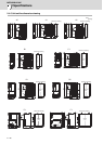
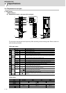
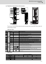
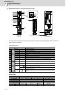
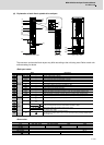
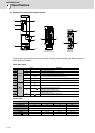
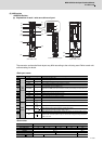
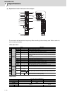
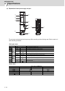
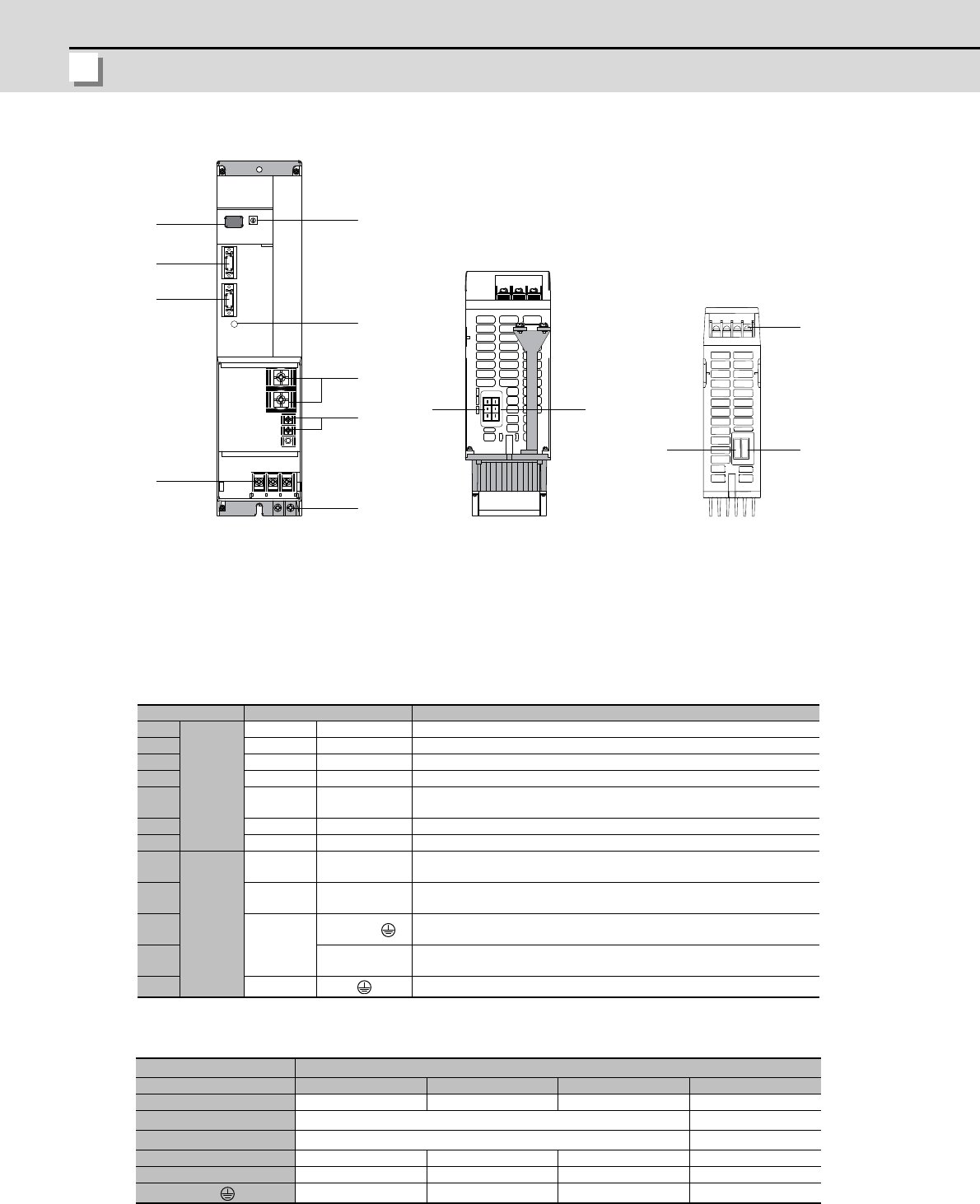
(e) Explanation of each power supply unit part
The connector and terminal block layout may differ according to the unit being used. Refer to each unit
outline drawing for details.
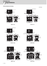
<Each part name>
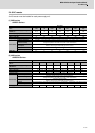
<Screw size>
Name Description
(1)
Control
circuit
LED --- Power supply status indication LED
(2) SW1 --- Power supply setting switch
(3) CN4 --- Servo/spindle communication connector (master)
(4) CN9 --- Servo/spindle communication connector (slave)
(5) ---
CHARGE
LAMP
TE2 output charging/discharging circuit indication LED
(6) CN23A --- External emergency stop input connector (Key way: X type)
(7) CN23B MC1,MC2 External contactor control connector (Key way: Y type)
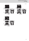
(8)
Main
circuit
TE2
L+
L-
Converter voltage output terminal (DC output)
(9) TE3
L11
L21
Control power input terminal (single-phase AC input)
(10)
TE1
L1,L2,L3,
Power input terminal (3-phase AC input),
Grounding terminal (for 60mm width)
(11) L1, L2, L3
Power input terminal (3-phase AC input),
(for 90mm width or more)
(12) PE Grounding terminal (for 90mm width or more)
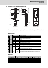
Power supply unit MDS-D-CV-
Type 37, 75 110,185 300 to 450 550
Unit width (mm) 60 90 150 300
(8) TE2 M6 x 16 M10 x 20
(9) TE3 M4 x 12 M4 x 8
(10) TE1 M4 x 12 - - -
(11) TE1 - M5 x 12 M8 x 16 M10 x 20
(12)
- M5 x 12 M8 x 14 M10 x 20
MDS-D-CV Bottom view
90mm width or more
Bottom view
60mm width
(6)
(7)
(2)
(3)
(9)
(12)
(1)
(4)
(5)
(8)
(10)
(11)
(7)
(6)