


MDS-D/DH Series Specifications Manual
2-4 Drive unit
2 - 65
(2) 400V series
< MDS-DH Series >
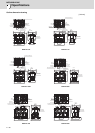
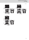
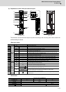
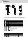
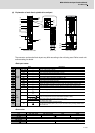
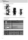
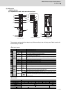
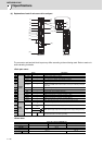
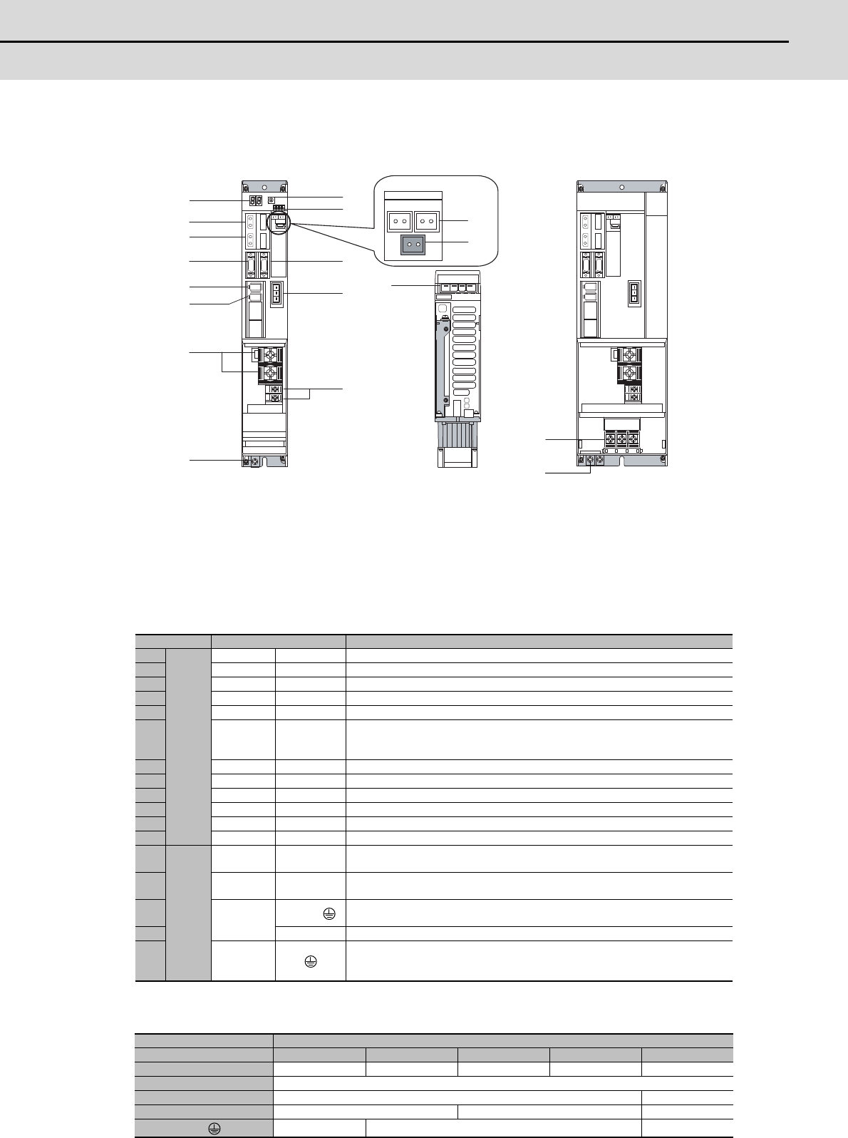
(a) Explanation of each 1-axis servo drive unit part
The connector and terminal block layout may differ according to the unit being used. Refer to each unit
outline drawing for details.
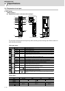
<Each part name>
<Screw size>
Name Description
(1)
Con-
trol
circuit
LED --- Unit status indication LED
(2) SWL --- Axis No. setting switch
(3) SW1 --- Unused axis setting switch
(4) CN1A --- NC or master axis optical communication connector
(5) CN1B --- Slave axis optical communication connector
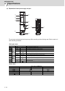
(6) BTA,BTB ---
For connecting converged battery unit
Both BTA and BTB are the same function, and they are internally connected each oth-
er.
(7) BT1 --- For connecting battery built-in drive unit ER6V-C119B
(8) CN9 --- Maintenance connector (usually not used)
(9) CN4 --- Power supply communication connector
(10) CN2 --- Motor side detector connection connector
(11) CN3 --- Machine side detector connection connector
(12) CN20 --- Motor brake/dynamic brake control connector (Key way: X type)
(13)
Main
circuit
TE2
L+
L-
Converter voltage input terminal (DC input)
(14) TE3
L11
L21
Control power input terminal (single-phase AC input)
(15)
TE1
U, V, W,
Motor power supply output connector (3-phase AC output),
Motor grounding terminal (for 90mm width or less)
(16) U, V, W Motor power supply output terminal (3-phase AC output) (for 120mm width or more)
(17) PE
Grounding terminal, Motor grounding terminal
Note that TE1 connector (above "(15)") is used for the motor grounding of the 90mm
width unit or less.
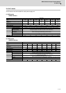
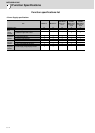
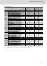
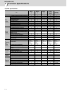
1-axis servo drive unit MDS-DH-V1-
Type 10 to 80 80W 160 160W 200
Unit width (mm) 60 90 120 150 240
(13) TE2 M6×16
(14) TE3 M4×12 M4×8
(16) TE1 - M5×12 M8×15
(17)
M4×12 M5×12 M8×16
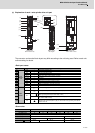
MDS-DH-V1
90mm width or less
Bottom view of left diagram MDS-DH-V1
120mm width or more
(2)
(3)
(4)
(5)
(1)
(9)
(12)
(14)
(17)
(15)
(8)
(10)
(11)
(13)
(6)
(7)
(16)
(17)