


6 Specifications of Peripheral Devices
MITSUBISHI CNC
6 - 14
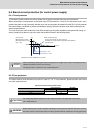
6-7 Relay
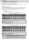
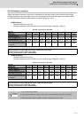
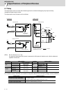
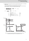
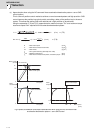
The input/output circuit to control the external signal such as external emergency stop input and relay
changeover signal output is wired.
The input/output circuit for each unit is as follows.
(Note) Do not connect "(1)" or "(2)".
If a ground of the external 24V power is same as the 24V power in the drive unit, a fault or abnormal
operation could occur.
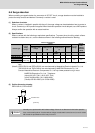
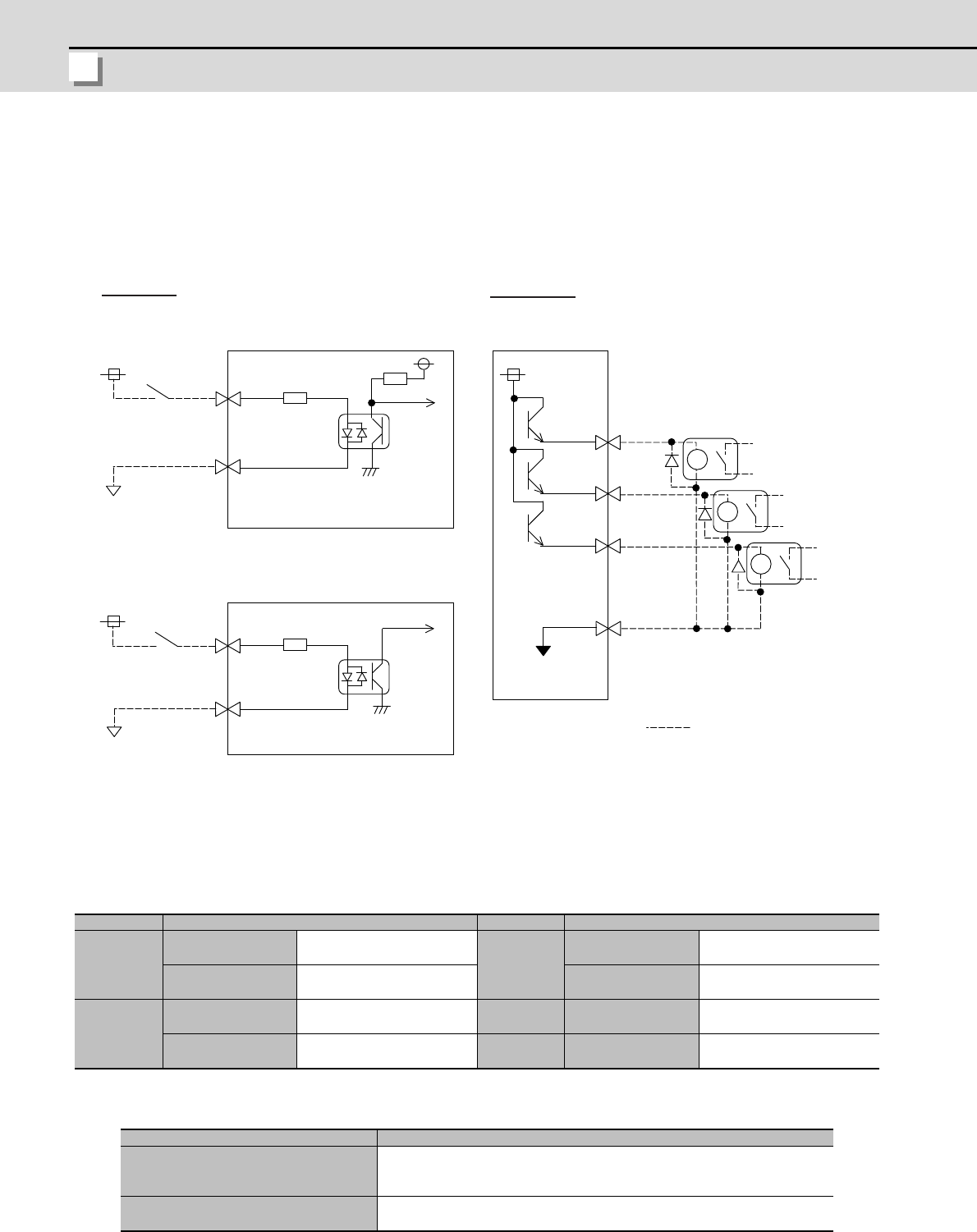
For a switch or relay to be wired, use a switch or relay that satisfies the input/output (voltage, current) conditions.
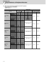
Connector Input condition Connector Output condition
CN9
Switch ON
18VDC to 25.2VDC
4.3mA or more
CN9
Output voltage 24VDC ±5%
Switch OFF
4VDC or less
2mA or less
Tolerable output
current to
50mA or less
CN23A
Switch ON
18VDC to 25.2VDC
9mA or more
Switch OFF
4VDC or less
2mA or less
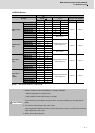
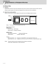
Interface name Selection example
For digital input signal (CN23,CN9)
Use a minute signal switch which is stably contacted and operated even with
low voltage or current.
<Example> OMRON: G2A, G6B type, MY type, LY type
For digital output signal (CN9)
Use a compact relay operated with rating of 24VDC, 50mA or less.
<Example> OMROM: G6B type, MY type
DICOM
DI1
13
20
3
1
2k
24V
24V
24V
(1)
8
18
16
10
MPO1
MPO2
MPO3
24G
D01
D02
D03
4.1k
(2)
CN9 connector CN9 connector
Servo/spindle
drive unit
CN23A connector
Switch
Power supply unit
Input circuit
Output circuit
Servo/spindle
drive unit
Relay, etc.
The part indicated by the " " must be
prepared by the user.
Switch